This is a guest post by David Underdown and is a revised and updated version of an article which first appeared in The Ringing World on 19 October 2012, pp1102–1104, 1106–1107.
Surrey Association of Church Bell Ringers First World War Roll of Honour – Lt J W Russell MC DCM MM RE, Dorking
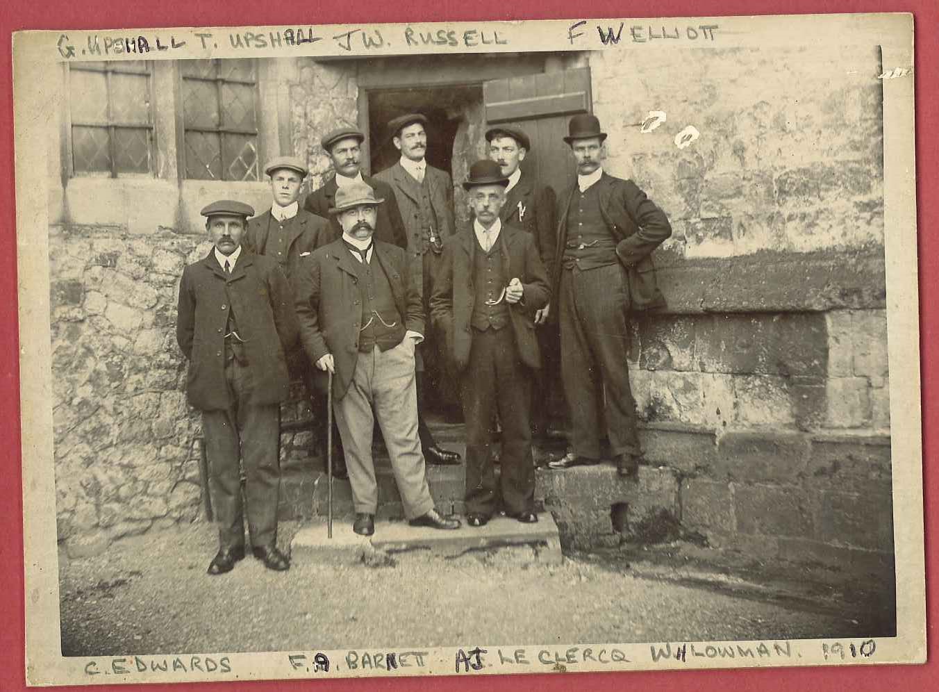
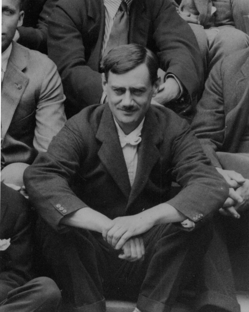
Peal band at Farnham, 25 May 1910, muffled peal of Bob Major to mark the funeral of King Edward VII that day. Russell is in the doorway at the back of the group.
A couple of years ago I begin to research the 152 men named on the Surrey Association’s roll of honour for the First World War. Of these, 24 died during the course of the war, the rest survived. The roll contains the names of a number of high profile ringers, but also many lesser known. A few names continue to defy all attempts to identify them in censuses, army records etc, but I’ve uncovered a number of interesting stories. In terms of his war service, perhaps the most interesting of them is the man who appears on the roll as J Russel of Dorking, but various clues soon led me to realise that he was in fact John William Russell. A simple gardener before the war: he would end it a lieutenant and holding one of the nation’s second highest awards for gallantry, the Distinguished Conduct Medal; two of the third highest decorations, both the Military Cross and the Military Medal; and was also Mentioned in Despatches. He served throughout with the Signal Service of the Royal Engineers.
John William Russell was born at Mickleham, Surrey, on 10 August 1887. The family must have moved to Ewhurst quite soon after, by 1891 they were living there, at Coneyhurst Lodge, and the census lists his 2-year-old sister, Catherine Annie as having been born in Ewhurst. His parents were John (28 – a gardener, born Tydd St Mary, Lincs) and Catherine (29, born Elgin, Scotland), John William often appears in ringing records as W Russell, suggesting he may have been known as William, so Catherine Annie may likewise have been known as Annie. He was educated at Ewhurst National School, but by the time of the 1901 census, he was 13 and working as a garden boy. By then the family had grown further, to include Ruth (9), Caroline Jane (7), Charlie (6) and Jessie (5).
It’s not clear exactly when Russell learned to ring, but he seems to have been elected to the Winchester Diocesan Guild in 1905, first appearing in the 1906 Annual Report as W Russell, Ewhurst, Guildford District. He is listed again as a Ewhurst ringer in 1907. He’s first mentioned in the ringing press in connection with ringing for the visit of the Bishop of Dorking to Ewhurst on 15 December 1907.
The next item to appear in Bell News didn’t mention Russell directly, but had considerable influence on his life and ringing. On 18 January 1908 the paper carried an advert by Charles Edwards for two men to work in his plant nursery at Frensham Hill, Surrey. Edwards was a Herefordshire man, but had moved to Surrey in 1905, and seems to have quickly started shaking up ringing in Farnham and the surrounding area. He was also particularly associated with Frensham: the bells there had been augmented to six for Victoria’s Diamond Jubilee, but it was only when ropeguides were fitted around 1907, and he began teaching some of the locals, that it became a strong band.

The advert which appeared in Bell News, 18 January 1908, p 519
It appears that the first journeyman position was taken by Frederick Walter Elliott (standing to Russell’s left in the photo at the head of the article). He rang a farewell peal at Little Munden, Hertfordshire, on 30 January, with a footnote saying he was moving to Frensham. His later Central Council biography matches this, and gives his occupation as gardener (also confirmed by the 1911 census). Edwards wrote to Bell News to thank those who had applied, and subsequently only the second part of the ad appeared. Russell rang at Frensham at the start of February 1908, and possibly this was also in the nature of a job interview. The ad reveals something of a large hurdle in his obtaining the job though – Edwards was looking for a man of 25-30 and Russell was just 20. However, I initially had trouble finding Russell in the 1911 census as he was listed as being two years older than his actual age, this gives a possible reason for that discrepancy, and it’s also instructive to compare his appearance in the 1910 photo with that of George Upshall, the only one of the men without a moustache, and actually two years Russell’s senior!
Russell is first mentioned ringing at Farnham at the beginning of March – though the 1908 WDG Annual Report still lists him as a Ewhurst ringer. He rang his first peal, of Bob Minor, at Frensham on 21 March, the first peal on the bells. The pages of Bell News show a large amount of activity for the rest of 1908: at Farnham and Frensham, and trips to other local towers.
1909 began with another peal at Frensham. This and the previous year’s peal are recorded on a fine peal board at in the tower there.
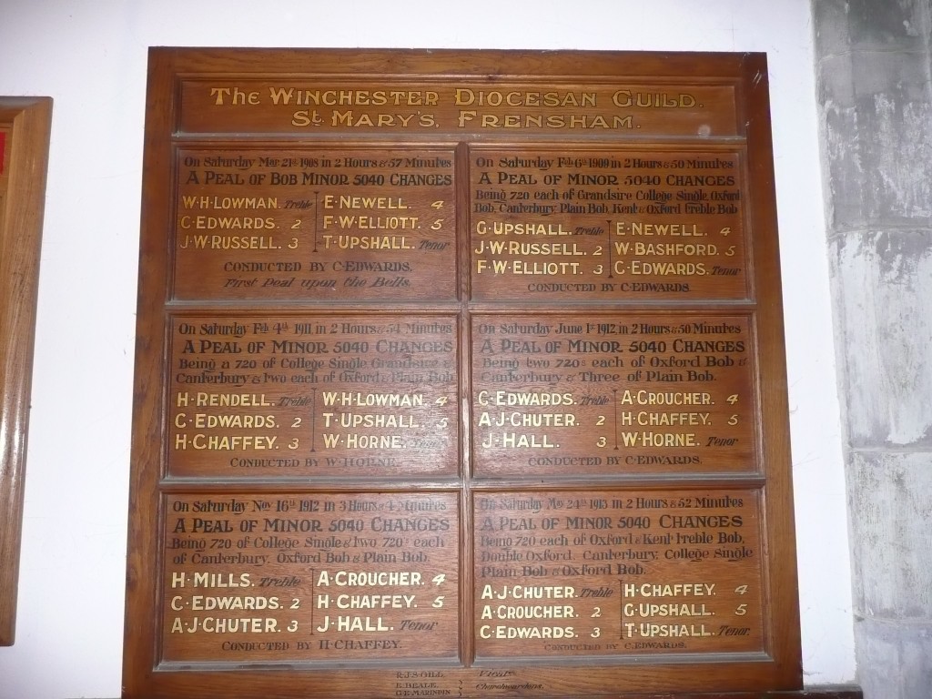
Frensham peal board
The rest of the year also followed a fairly similar course to 1908: various ringing at Farnham and Frensham, and trips elsewhere in the local district. His recorded ringing in 1909 concludes in October, when it appears he made a visit home, attending practice at Ewhurst on 15 October.
1910 saw a distinct drop in Russell’s recorded activity. In the first half of the year he rang in two half-muffled peals at Farnham, the first, of Grandsire Triples on 19 February, in memory of the well-known ringing cleric theRevd F E Robinson. The second, that of Bob Major on 25 May for the late King, following which the peal band was photographed for posterity. This was noted as being the first peal of major by an entirely local band since 1806, and was accorded a fine entry in the tower peal book. This is his last recorded ringing at Farnham.
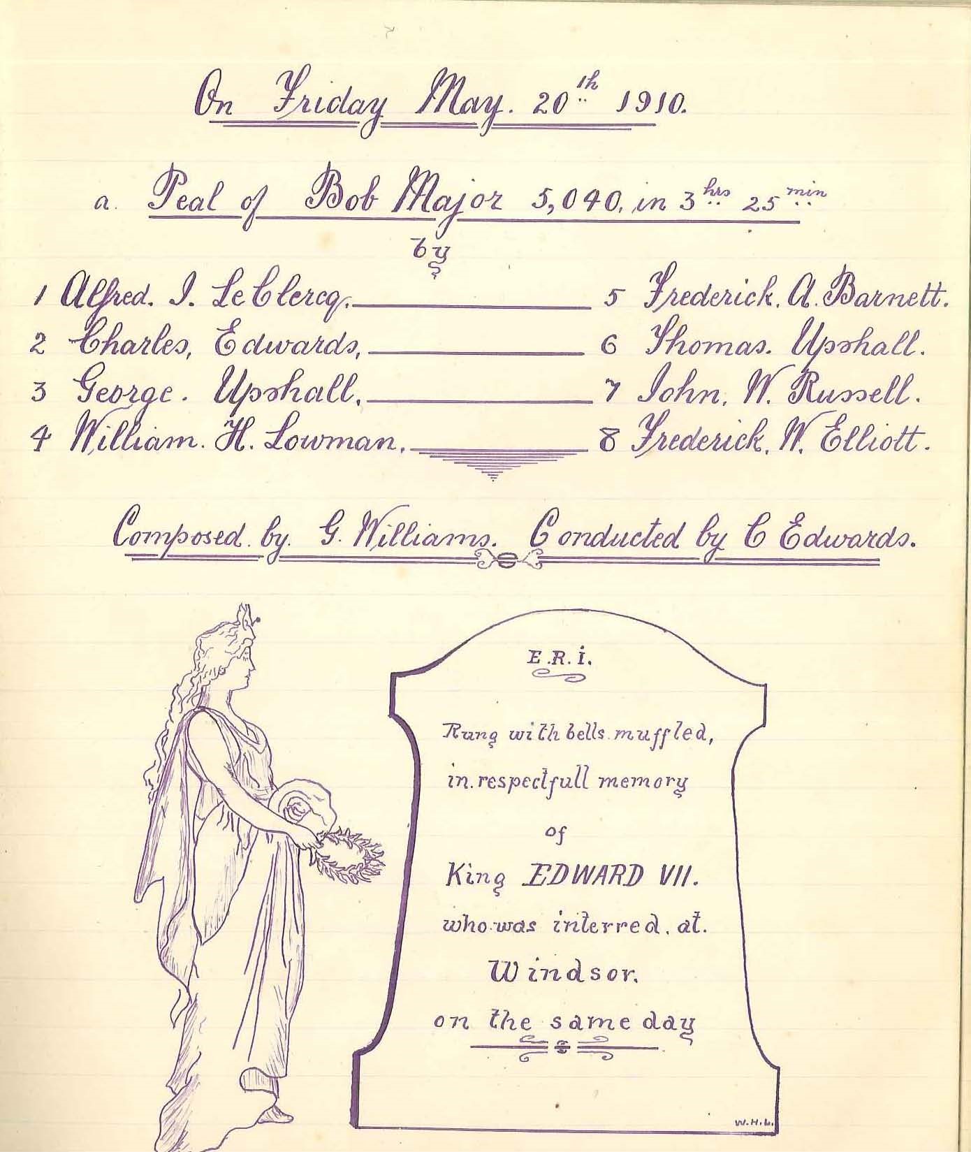
Farnham Peal Book entry
The Winchester DG Annual Reports for 1910-12 note Russell as a compounding (i.e. non-resident) member, living at Standen, Sussex. On 6 November 1910 he rang a peal for the Sussex County Association at Crawley, having been elected to the association before the start of the peal. The 1911 census (taken at the start of April) shows him as the head of the household, living at Stone Farm Lodge, Standen, with two other gardeners. As mentioned earlier, his age is shown as two years older than his actual age, and since he was the head of the household we can be reasonably sure he completed the form himself – the writing also appears similar to later army forms. Stone Farm was one of three farms purchased by James Samuel Beale in 1890 to form a country estate he named Standen, now a National Trust property. Beale’s wife, Margaret, was a keen gardener.
It appears that Russell moved back to Surrey sometime in 1912, probably to work in Abinger. One of the referees on his application for a wartime commission was Lady Mirrielees, who lived at Pasture Wood, Abinger. The membership records of the Ancient Society of College Youths record that John William Russell of Abinger was elected a member in 1912 (http://www.ascy.org.uk/mem1900-1924.htm). He visited old haunts at the end of August, finally scoring a peal at Bentley. On 6 November he rang in a College Youths’ peal of Stedman Triples at Ashtead, Surrey (his first of Stedman); on 19 December he rang a peal of Grandsire Triples at Dorking, this commemorated the laying of the foundation stone for a new chapel. This chapel seems to have proceeded rapidly; on 14 March 1913 there was another peal of Grandsire Triples to celebrate its dedication. This is the last record I have found of Russell as an active ringer, though a letter of his published in The Ringing World during the war suggests he had continued involvement in ringing until going overseas.
Russell joined the Royal Engineers at Aldershot on 11 September 1914, just over a month after the outbreak of war. He had been medically examined two days previously, reverting to his correct age, given as 27 years and 1 month. The medical officer described him as being 5’8¼” – relatively tall for the time, having a 36” chest (with 2” expansion) and weighing 156 lbs, with dark hair, a fresh complexion and blue eyes. When signing up, he described himself as a fitter, rather than a gardener, but this seems to have been another attempt to improve his chances, there is no sign in his papers that he was given a trade test, and he was given the rank of pioneer initially, indicating that the army did not view him as a skilled tradesman (who were ranked as sapper). In his subsequent application for a commission, he once more describes himself as a gardener.
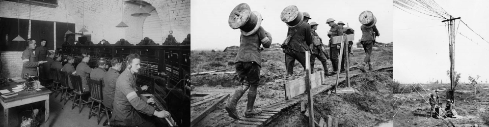
Official records do not give much information as to Russell’s initial training, however, The Ringing World published regular updates on ringers serving with the forces, and the issue of 9 October 1914, p199, listed “J. W. Russell of Ewhurst, Surrey, Royal Engineers, now at Chatham” – Chatham has been the home of the Royal Engineers for centuries. After his training, he was transferred to 24th Divisional Signal Company (signals had not yet been established as a separate corps, and were an RE responsibility) on 22 October 1914. 24th Division was one of the divisions of Lord Kitchener’s New Army – virtually all the men and officers had to be trained from scratch. The bulk of the infantry battalions making up the division were recruited from the South East and East Anglia, men Russell would have felt at home with. The signal company was divided into four sections, one with divisional HQ, and one each which of the three brigades it comprised. Russell was in the section attached to 72 Infantry Brigade (72IB), the other two brigades were 71 IB and 73 IB. Russell himself seems to have taken full advantage of the opportunities this situation gave to hard-working men: he was appointed lance corporal on 21 November 1914, then promoted second corporal on 10 December, corporal on 6 January 1915 and serjeant on 2 March. Page 143 of the 15 March 1915 issue of Ringing World tells us “J. W. Russell, of Abinger, Surrey, and formerly of Farnham, has had rapid promotion, and has now gained the rank of sergeant.” The division had initially been based along the south coast, principally at Worthing and Shoreham, but in June 1915 they moved to the Aldershot area – familiar territory for Russell.
His personal life was also about to undergo a big change, sometime during this period (presumably) he met Rosetta Pickard, and they married in her home church of St Michael, Tilehurst, near Reading on 19 August 1915. The same day, most of the division was being inspected by Lord Kitchener at Chobham, and formal orders for France were received from the War Office. King George V carried out another inspection the following day. On 30 August, the signal section boarded a train at Farnborough for Southampton, and thence Le Havre, and he was in France on the following day. By this time, planning for a major British offensive around the northern French mining town of Loos was well under way: despite the fact the British high command were aware that they were short of men, heavy artillery and shells; the politics of the alliance with France made it imperative that a “Big Push” was launched. 24th Division was in reserve for the opening of the offensive on 25 September, having spent several days marching up from positions behind the lines. From the early hours of 26 September, they made their way up to the front lines, and were committed to action around 8am. By now German forces were already preparing major counter-attacks. The fighting dragged on until 18 October, but in reality – after some missed chances on the opening day – the British were never going to reach their objectives. The four infantry battalions in 72nd Brigade: 8th Royal West Kents, 8th Buffs (East Kents), 9th East Surreys, and 8th Queen’s (Royal West Surreys) had casualties (killed, wounded and missing) of respectively: 556 other ranks, 24 officers; 534 other ranks and 24 officers; 455 other ranks, and 22 officers; and 427 other ranks and 12 officers; each having committed around 670 men and just under 30 officers. In all, 50 battalions lost over 300 men, and 23 more between 200 and 300. In the midst of this baptism of fire, Russell had a vital role to play in attempting to keep communications flowing from 72nd Brigade up to the Divisional HQ (and vice-versa). He described a little of his own experiences in the battle in a letter which formed part of an article in The Ringing World of 15 November 1915, p 219:
RINGER’S EXPERIENCES IN BELGIUM.
Writing from “somewhere in Belgium,” Sergt. J. W. Russell, Signal Section 721 B [sic – should be 72 IB], formerly of Dorking, and a member of the Winchester Guild, says, in a letter to Mr. F. E. Dawe [presumably Francis Edward Dawe of Woking, a Past Master of the College Youths, and first Hon Sec of the Central Council, and conductor of Russell’s College youths’ peal in 1912], that since he left England on August 31st he has spent a lot of his time in travelling up and down the western front. “My first action,” he continues, “was what is known in the papers as the ‘great advance,’ and since that we have been in a different part of the front altogether. Of course you must understand that we do not spend the whole of our time in the trenches. Personally, I have only spent two whole nights in them during the whole time, although some of my men are in the trenches throughout the period we are ‘up,’ as it is called. I spend more of my time, nights especially, at headquarters, although even there we are often in the danger zone, especially if the enemy gets ‘jumpy ‘ enough to let loose his heavy artillery- then the safest place is a dug-out.
“It is difficult to describe the amount of damage done to t he country by heavy gun fire. In some places whole villages are practically levelled to the ground, just a base wall standing here or there, but no semblance of a house, and of course the ground around it is nothing but a series of holes that may be anything from 2ft. to 30ft. in diameter and up to 10ft. in depth. Undoubtedly the enemy’s guns are capable of doing an enormous amount of damage, although I think that now we have just about got their measure in that respect, and can hold our own easily.
“How is ringing progressing? I suppose it is as quiet, as ever. One thing I am pretty certain of and that is that a good many of the good bands will never meet again. I am afraid I am getting quite, an outsider now, for I haven’t seen a. ‘Ringing World ‘ since coming out.
“We had his Majesty the King to visit us one day recently. I was lucky enough to be in the guard of honour. I thought he was looking very well indeed, considering the weight he has to carry just now. The Prince of Wales is making good out here.”
He had evidently done his job well, as it was in Field Marshal French’s despatch covering this action that he received his first gallantry award, a Mention in Despatches, which appeared in the London Gazette on 1 January 1916. This may have been the reason he was chosen to form part of the King’s guard of honour. The ceremonial inspection took place at Reningelst, Belgium (approximately 5km SSE of Poperinge and 10km WSW of Ieper/Ypres) at 11:30am on 27 October. They had been pulled out of the Loos area on 27 September and sent north to Belgium to refit. 71 Infantry Brigade was replaced by the regular army 17 Infantry Brigade (though of course by this time few of the pre-war regulars remained), and one battalion each of 72 and 73 Infantry Brigades was then exchanged for a regular battalion from 17 IB.
He continued in the same vein, receiving the DCM in the King’s Birthday Honours gazetted on 3 June 1916, though the citation was not published until 21 June: “For conspicuous and consistent good work on his system of telephone lines. He has shown tireless energy and resource, besides great gallantry, under fire.” In addition, though he received no further promotions, signallers could obtain increased pay by improving their skill in their designated trade, Russell’s record shows he was rated “proficient” on 20 September 1915, “skilled” on 20 March 1916 (and would ultimately be rated “superior” on 20 September 1916). The division had spent this entire period in Belgium, much of it around the Ypres Salient. Though there were no major battles, there was constant shellfire, and some fairly serious poison gas attacks by the Germans. Telephone and other communication cables were frequently broken and had to be repaired quickly, even if the shelling hadn’t stopped.
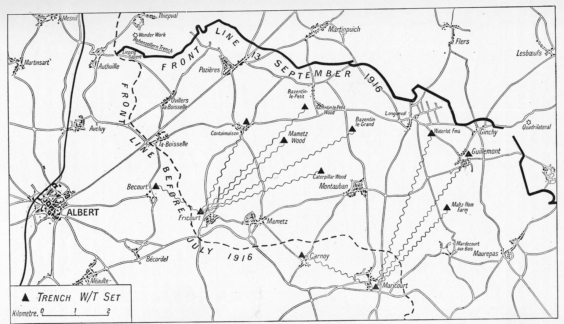
In mid-July the division returned to France, ordered to the Somme to relieve the units which had begun the battle there on 1 July. They fought in the Battle of Delville Wood, and the last German forces there fell back on 3 September after a long fight, and 72 IB was involved to the very end. The Division then took part in the subsequent Battle of Guillemont which helped to stabilise the British hold on the area.
Russell was hospitalised from 23 February-6 March 1917, no reason is given in his records – the company war diary shows 13 men were admitted to hospital in February 1917, and four were still there at the end of the month; most of the month was spent in training, so it is unlikely it had anything to do with enemy action. After returning to his unit, Russell was granted home leave from 16-26 March – this was presumably the first time he had seen his wife in 18 months. By now, planning was well under way for another major offensive in the Arras area. The task of taking the strategically important Vimy Ridge had been allocated to the Canadian Corps who had been training for months, and under the ground was a maze of tunnels. The attack was due to be launched on Easter Day, 8 April 1917, but in the event was delayed by a day at the request of the French, who were to launch another attack further south, one purpose of the British attack being to draw in German reinforcements and thus weaken the defences in the area the French were to attack. On 9 April, 24 Division was holding the trenches from which the Canadians launched their attack, and so suffered badly in the German counter-bombardment. The initial few days of the offensive were a great success, but momentum gradually slowed. By 13 April the division was slightly further north, almost on the same ground as they had fought over at Loos on their first arrival in France. At 2.55pm on 13 April, Divisional HQ signalled to 72 Infantry Brigade that the Germans seemed to be making a full-scale withdrawal. Over the next few days, the division moved forward to take over the old German trenches.
It was probably for actions at Arras that Russell recommended for the Military Medal, which was gazetted on 21 July. No citations were published for these awards, and unfortunately the company war diary never mentions any of Russell’s awards while he was a serjeant, though some awards to other men are mentioned, so it’s impossible to be sure, but the rule of thumb among WWI researchers is that medals followed around three months after the action concerned. By then the division was back in Belgium and had fought in the Battle of Messines from 7-14 June, preparations for this action had begun over a year earlier with major mining operations, the attack opened with one of the largest non-nuclear explosions in history, when explosives packed into the tunnels were set off immediately under the German frontlines. Early in July, Russell’s company commander recommended him for a commission. Russell was interviewed by the Deputy Director of Signals, Second Army (a full colonel) on 10 July, who approved the application. On 31 July the Third Battle of Ypres began (better known by the name of one of its sub-phases, Passchendaele). The division was involved in the Battle of Pilkem from 31 July to 2 August, and then the Battle of Langemarck from 16 to 18 August.
Inevitably there was a fair amount of paperwork to sort out before the commission became official. Applicants were also expected to give two character references, in this case Lady M Mirrielees of Pasture Wood, Dorking (the family also owned Goddard’s at Abinger Common) and the Revd A E Clark-Kennedy, the Vicar of Ewhurst. Formalities complete, he was commissioned as a temporary second lieutenant on 2 September 1917, continuing to serve with 24th Divisional Signal Company. The division’s final major action of the year was at the end of November, defending against German counter-attacks in the Battle of Cambrai.
Officers are generally named more frequently in unit war diaries, but Russell still rarely appears. However, we can be reasonably sure that the actions for which he won his final decoration, the Military Cross, took place during the German Spring Offensive, launched in March 1918. The British Army went into full retreat, and nearly broke, leading to Haig’s “Backs to the wall” order, but in the end the line was stabilised – though significant territory was lost to the Germans. The MC was not gazetted until 16 September 1918, the citation read: “For conspicuous gallantry and devotion to duty during operations lasting for several days, when he was continuously out laying telephone lines from divisional advance headquarters to brigade headquarters, frequently under heavy fire. On one occasion, when one of the brigades was nearly surrounded, he, although under heavy machine-gun and shell fire, succeeded in keeping through telephonic communication to the brigade, which greatly contributed to the ultimate success of the operation.”
24 Division played a heroic part in the defence, particularly in and around the town of Le Verguier (about 20km west of Péronne) on the opening day of the German offensive, 21 March, here there is a street named after the division, Rue de la 24éme division Britannique. Even more unusually, the division is named on the town’s own war memorial.
That was the German’s last attempt to win the war, begun in the knowledge that US forces were building up in earnest, and that they had to try and strike a decisive blow before the strategic advantage changed hands. Soon the momentum was with the Allies who begin a steady advance during the “100 days” which finished the war with the coming into effect of the Armistice at 11:00am on 11 November 1918. This did not bring Russell’s service to an immediate close, as 24th Division formed part of the Army of Occupation which was sent into Germany and remained there until the end of May 1919. Even then, Russell continued to serve at home, perhaps he actually considered taking a permanent commission, but it seems that ultimately he either found peacetime soldiering dull, or there simply wasn’t the requirement for a ranker officer in the reduced army. On 12 May 1922 he relinquished his commission. His discharge documents show he gave his permanent address as Coneyhurst, and despite calling himself a “fitter” when he originally joined up, here he states his occupation as “Landscape Gardener”. His final posting had been with a signals unit of Southern Command at Portsmouth, he remained a Royal Engineer, but was attached to the brand new Royal Corps of Signals on its formation. Another possible reason for his deciding to leave the army was the birth of a daughter, Olive Betty, whose birth was registered in Portsmouth in the third quarter of 1921.
Russell’s contact with the War Office had not quite ended. He was entitled to a war gratuity for the period he served in the ranks, but owing to his late demobilisation, and confusion with another J W Russell he had to fight to receive it, the Royal British Legion having to step in on his behalf. The correspondence in his service file relating to this shows that by 1923 he was living in Ringwood, Hampshire. It appears his wife died in late 1926, aged just 41, in the Bournemouth area. I have not been able to much information about his life in Hampshire: he does not re-appear in the membership lists of the Winchester DG prior to the Second World War, so he probably did not return to ringing at this time. Local directories from 1930, 1934 and 1945 give his address as Grange Estate, St Leonard’s (the first of this actually states Mrs J W Russell, presumably a typo). Local ringing records do show a J Russell ringing the tenor to a touch of Stedman Doubles on 19 March 1946. It seems likely this is the same man, but there is no definite proof. Russell died, sadly, on Christmas Day 1946, aged 59. The causes of death are given as (a) cerebral embolism and (b) mitral disease [of the heart]. Olive was present at the death, which took place at Grange Estate, St Leonard’s and St Ives Rural District (near Ringwood). His occupation is recorded as “Contractors’ Foreman (Engineer)”. He was buried at Ringwood Cemetery on 28 December 1946 in grave D/D 249. The burial records describe him as “Clerk of Works, retired”.
Probate was granted in London on 4 June 1947, to his executor, Douglas George Oliver, a market gardener. He left an estate of £990 6s 6d (equivalent to around £134,000 today, as a share of GDP). His will, drawn up in 1938 makes prominent mention of Daisy Elizabeth Dymott, given her choice of ornaments and furniture, a joint share of the house with Olive (unless they decide to sell it, in which case Olive would get all the proceeds), and to act as Olive’s guardian had Olive still been under-age. Daisy appears never to have married, also born in 1881, the 1911 census records her living with her parents in Southampton and employed as a geological examiner. She probably simply helped to look after Olive after Rosetta’s early death.
Olive seems to have married Ernest C White (a civil servant) in 1953 and lived in Wimborne Minster until her own death in 1960 aged just 39, even younger than her mother. A Rosemary A White, with a mother’s maiden name of Russell, was born in the Poole registration district (which then included Wimborne) in 1957.
The four gallantry awards he received make him comfortably the most decorated member of the Surrey Association to have served during the First World War. He may well be the most decorated ringer of the war – one ringer, Serjeant William Johnson of Worksop Priory, is known to have been awarded the Victoria Cross, and a few others received the DCM or MM and Lt-Col Charles Frederick Jerram, Royal Marines Light Infantry was Mentioned in Despatches five times, awarded the DSO and appointed CMG (and awarded the French Croix de Guerre), largely for staff work, but I have not seen any other with so many gallantry decorations. I was able to photograph Russell’s service record, the images can be seen at http://flic.kr/s/aHsjuG8kwe.
I am grateful to the librarians of the Winchester DG and Sussex County Association, Bruce Purvis and Stella Bianco, for checking annual reports; Alan Baldock the Sussex peal secretary for details of Russell’s one peal in Sussex; Paul Whewell and David Munro of Farnham and Frensham respectively (and the other ringers there) for providing photos of peal records, and the photo of the man himself; and Christine Wright of Ringwood for information from local directories, tower records, and the burial records. Apologies if I have omitted anyone who provided me with information.