Tag Archives: Keith Thrower

Guest post by Keith Thrower: Technical factors affecting CW radio communication in WW1, part 3

Summary: This paper summarises the factors that affected the development of CW radio communication during the period up to 1918. It shows that most of the important circuits had been invented by 1914. The major technical factor affecting the successful development of CW radios for battlefield communication was the unavailability of robust radio valves: these did not become available until late in 1915 with the introduction of the French TM valve. Up until that time almost all radios were spark transmitters and crystal detector receivers.

Full version of the paper: Technical factors affecting CW radio communication in WW1 [pdf] Part 1 Part 2

Circuit development up to 1914

  1. Oscillator

Several people have claimed the invention of the valve oscillator but priority was given to Meissner who took out a German patent in April 1913 [21, 22]. Two important by-products of this invention were the heterodyne circuit and regenerative feedback (sometimes called reaction).

Significant improvements in oscillator design were made by Hartley and Colpitts, both working for Western Electric.

  1. The heterodyne

The heterodyne receiver was patented by Reginald Fessenden in 1901 [23]. The patent shows the use of two alternators at the transmitter connected on a common shaft and differing slightly in frequency. The outputs from these were each connected to separate antennas. At the receiver there was, likewise, two antennas and these were connected to coils wound on an iron core with a telephonic diaphragm at one end. In 1905 Fessenden applied for a further patent where he used one alternator in the transmitter and one in the receiver, the two frequencies being adjusted to produce an audible signal in the headphones [24].

A further improvement was made by Lee and Hogan in November 1912 when they used an alternator (or arc generator) in the receiver and a crystal detector [25].

The advantage of the heterodyne receiver was shown in the US naval trials from the Arlington station to the USS Salem, which commenced on 15 February 1913 [26, 27]. The trials compared the performance of the heterodyne receiver against that of a conventional crystal receiver and one using a ‘ticker’ to break up the incoming CW signal into short bursts.

A further improvement was made by Henry Round of the British Marconi Company with the invention of the Autodyne receiver which he patented in December 1913 [28]. The Autodyne was a self-oscillating mixer where the frequency of the oscillator was adjusted to differ slightly from that to the incoming signal. The valve used was the Marconi type C, soft triode.

  1. Regenerative feedback (reaction)

Edwin Armstrong had been seeking means to improve the sensitivity of the audion receiver which he had built as a student at Columbia University. He achieved this by regenerative feedback from the anode circuit to the grid circuit, the feedback being adjusted to just below the point of oscillation. This form of feedback became known as reaction. His circuit was witnessed by a notary on 31 January 1913.and he applied for a US patent later that year [29].

In Britain the Marconi engineer Charles Franklin patented his regenerative receiver circuit on 12 June 1913, four months before Armstrong. Franklin, it would appear, was the first person to note that the regenerative action increased the input impedance of the valve and thereby reduced the loading on the tuned circuit [30].

  1. RF amplifier

Although the triode valve had been invented by Lee de Forest at the end of 1906 it was not used successfully as an amplifier until 1911. The earliest recorded amplifier using the audion valve would appear to be that of Otto von Bronk, a Telefunken engineer who applied for a German patent on 2 September 1911 [31]. The circuit shown is of an RF amplifier (without grid blocking capacitor as used by de Forest in his detector and early attempts to produce an amplifier). The output from the valve is shown connected by an RF transformer to a crystal detector and telephone earpiece.

Conclusions

  1. Before the outbreak of WW1 in August 1914 many of the circuits to be used in later years for CW radio communications had already been invented, although most of these were still at an early stage of practical applications. These circuits include the radio wave detector, the oscillator, the heterodyne, the RF amplifier and regeneration.
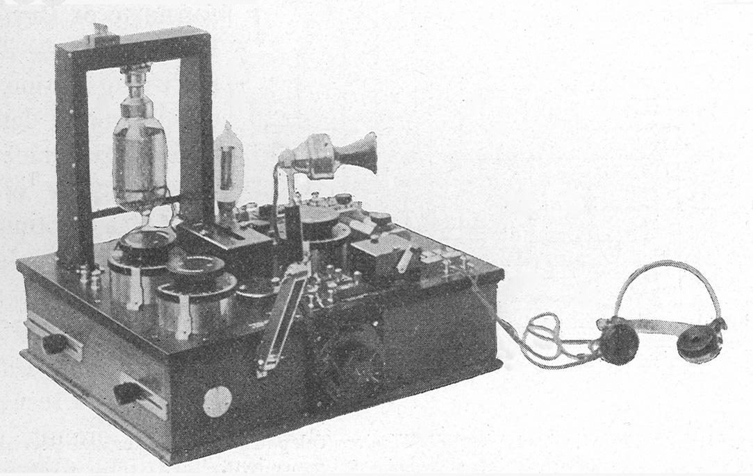
  2. The British Marconi Company embodied all of these in the Marconi Short Distance Wireless Telephone Transmitter and Receiver which was produced in 1914 and used on ship-to-shore trials.
  3. There were few valves available in 1914 for use in radio equipment. The de Forest audion was erratic in operation, fragile and had a short filament life. The Marconi soft valves, the C and T, were produced in 1913 and used in the radio mentioned in the previous paragraph. The C was a receiver valve and the T a transmitter valve. Both of these were difficult to manufacture and not suitable use on the battlefield. Apart from this the T valve required a power of 6-volts, 4-amps for its filament which meant very frequent replacement of the storage battery. Also an HT of several hundred volts was required.
  4. One important application of the Marconi C valve was in direction finding receivers and these continued to be used throughout the War until suitable hard valves became available from 1916.
  5. Until more robust valves became available the only way to communicate by radio from the trenches was by spark transmitters and crystal detector receivers. The transmitted signal from the spark transmitters was noisy and rich in harmonics which were spread over a wide spectrum. This meant that the radios had to be widely separated to prevent mutual interference.
  6. Even so it might have been possible to deploy a small number of an improved version of the Marconi Short Distance Wireless Telephone Transmitter and Receiver for use in Headquarters and some vehicles, but this did not happen.
  7. The situation changed dramatically with the introduction of the French TM valve in the early months of 1916. These valves were not well suited for use as RF amplifiers, except, maybe, at frequencies below 600 kHz. They were, however, well suited for use as radio detectors and audio amplifiers, not just in radios but also for the amplifiers required for the power buzzers. A valve more suitable as a detector and, possibly, as an RF amplifier was the Marconi Q. However, this valve proved difficult to manufacture in large quantities.
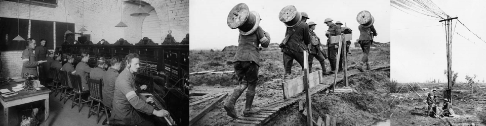
  8. It is well documented that there had been a reluctance in the Army to adopt radios and there was too much reliance on line communication, even though the cables were being constantly destroyed. Some of this reluctance was probably due to the problems of using spark transmitters in the trenches which were cumbersome and required skilled operators for the Morse transmissions. Their aerials also marked the position of the radios for enemy gunfire.
  9. The most obvious places for CW radios were in aeroplanes, motor vehicles and tanks and there should have been a concerted programme to design and manufacture radios for these.
  10. For use in trenches the requirement would have been for portable radios and these would have been required in large numbers during the last two years of the War.
  11. It is difficult to assess how many radios could have been produced by the British and French in the last two years of the War. The manufacturing companies would have been short of skilled labour and engineers because of the enormous toll of lives that had taken place, particularly of those men in the Signal Service.

References
21. Tucker, DG, ‘The history of positive feedback’, The Radio & Electronic Engineer, 42, No. 2, February 1972, pp.69–80.
22. Meissner, A, German patent, appl. 10 April 1913.
23. Fessenden, RA, US patent, 706,740, appl. 28 September 1901.
24. Fessenden, RA, US patent, 1,050,728, appl. 27 July 1905.
25. Lee, JW & Hogan, JL, US patent 1,141,717, appl. 16 November 1912.
26. Howeth, Capt. LS, History of Communications-Electronics in the United States Navy. Washington; 1963, pp.182–4.
27. Hogan, JL, ‘The heterodyne receiving system and notes in the recent Arlington-Salem tests’, Proc IRE, 13, July 1913, pp.75–102. (Note: Hogan worked for Fessenden at NESCO).
28. Round, HJ, British patent 28,413/13, appl. 9 December 1013.
29. Armstrong, EH, US patent 1,113,149, appl. 29 October 1913.
30. Franklin, C, British patent, 13,636/13, appl. 12 June 1913.
31. Von Bronk, Otto, German patent, 271,059, appl. 2 September 1911.

Guest post by Keith Thrower: Technical factors affecting CW radio communication in WW1, part 2

Summary: This paper summarises the factors that affected the development of CW radio communication during the period up to 1918. It shows that most of the important circuits had been invented by 1914. The major technical factor affecting the successful development of CW radios for battlefield communication was the unavailability of robust radio valves: these did not become available until late in 1915 with the introduction of the French TM valve. Up until that time almost all radios were spark transmitters and crystal detector receivers.

Full version of the paper: Technical factors affecting CW radio communication in WW1 [pdf] Part 1 Part 3

Marconi Short Distance Wireless Telephone Transmitter and Receiver

Marconi Short Distance Wireless Telephone Transmitter and Receiver

5. The Marconi Company

The Marconi’s Wireless Telegraph Company (MWT) never manufactured radio valves. All the valves that they used up to 1919 were either manufactured by the Edison Swan Electric Company (Ediswan) or by the Osram-Roberson Lamp Works of the British General Electric Company (GEC).

In 1919, Marconi’s and GEC decided to set up a joint company for valve design and manufacture that could benefit from their pooled know-how and valve patents. The company was incorporated on 20 October of that year and was originally called Marconi-Osram Valve Co. Ltd., but the name was changed in the following year to M.O. Valve Co. Ltd. (MOV). Production was at the Osram-Robertson Lamp Works and included many of the types previously manufactured by Ediswan.

6. The Marconi-Round ‘soft’ triodes

Towards the end of 1911, Henry J Round of the Marconi Company commenced the design of a diode valve. Because of other commitments, however, this activity was suspended until November 1912, when Round extended his earlier work to include both diode and triode valve development. There is good reason to believe that the design of these valves was influenced by the soft valve development of von Lieben, Reisz and Strauss, as a result of a technology exchange agreement between the Marconi and Telefunken companies.

The first successful soft valves of Round were manufactured by Ediswan in 1913. Amongst the earliest of these were the type C, a receiver valve, and the type T, a transmitter valve, both of which were used in World War 1 in various items of radio equipment (see below). The type C had a platinum wire filament, which was oxide coated; the grid was of fine mesh nickel wire that fully surrounded the filament, and the anode was a solid nickel cylinder.

A distinctive feature of the C valve (and indeed of most of the other Round soft valves) was a glass extension tube at the top of the bulb which contained a wad of asbestos. As time progressed, the gas pressure in the valve tended to fall, resulting in a loss of sensitivity. In order to raise the gas pressure to an optimum value, it was necessary to heat the asbestos, either electrically, or by holding a lighted match close to the extension tube, which released occluded gas into the enclosed glass bulb.

The type T transmitter valve had three filaments of tungsten or platinum wire. According to Picken ‘Although usually classed as a soft valve, it was actually exhausted as thoroughly as its construction and vacuum technique available permitted. The pellet at its extremity was inherited from its prototype, the soft receiving valve, and was an unnecessary appendage’ [14]. Some of the valves were manufactured without an extension tube at the top; instead they had a metal cap which was used as a top support

The type TN was introduced in 1914. This valve, together with the type C, was used in the Marconi Short-Distance Wireless Telephone Transmitter and Receiver (Early in 1914, the two Marconi engineers, Round and Tremellen, used the type T valve to transmit voice signals over a distance of 70km, probably using equipment similar to this.) [15].

According to Dowsett the TN was a soft valve and fitted either with two lime-coated platinum filaments or plain tungsten filaments. This meant that a comparatively high anode current could be obtained without using a very high anode voltage.

Other soft receiving valves made for the Marconi Company by Ediswan were the types CA, CT, D and N. Amongst the small transmitter valves, apart from the Type T, there were also the LT and TN.

There is little doubt that the Round soft valves were very difficult to manufacture, but during the early years of World War 1 there were no suitable alternatives. To quote from Round [16]:

It was probably fortunate in the first year of our work that we used the soft valves because no hard valve had been constructed which can compare with these ‘C’ type tubes as high-frequency magnifiers. These necessitated, however, trained men in their manufacture, and trained operators for their efficient use … Again and again we lost the knack of making good tubes, owing to some slight change in the materials used in their manufacture. A thorough investigation was impossible, as all hands were out on the stations. On several occasions we were down to our last dozen tubes.

The principal use of the C valve during WW1 was in a single-valve direction-finding equipment where its sensitivity was equivalent to three of more of the French TM valves in cascade. (See next section of this paper.) These DF receivers were mainly located around the south and east coasts of England and some were also located on the European mainland.

The T valves was used in some radios of the Royal Flying Corp but little information has been found on these. The equipment identified were a W/T 120-watt ground set covering the wavelength 600 to 1000m and used as a tonic train transmitter. There was also another ground station version of this which was used for wireless telephony. Dates of installation and quantities produced are unknown but there would have been used in small numbers, probably from 1916.

7. The French TM triode

One of the most important of the early European triode valves was a device developed under Colonel (later General) Gustave Ferrié who was in charge of the French Military Telegraphic Service during World War 1. The valve, which came in two slightly different constructions known as the ‘S’ and Métal, was developed from an audion sample that was brought to France in August 1914 by Paul Pichon [17]; it had a straight tungsten filament of length 21mm, a spiral grid with 11 or 12 turns made either of molybdenum or nickel of length 16mm by 4.5mm diameter, and a cylindrical nickel anode 15mm long by 10mm diameter. The filament rating was 4-volts, 0.65-amps. A patent application for the valve was taken out in October 1915 [18]. It was immensely successful and widely used during World War 1, during which time over 100,000 were manufactured by the two French companies, Fotos and Métal.

The TM was a hard valve, evacuated to a low pressure, and during the manufacturing process the glass and metal parts were heated to a sufficient temperature to release the occluded gases. An interesting feature of the valve was the use of a four-pin base, which later became a standard throughout Europe, including Britain. The electrodes were mounted on a glass stem inside a spherical glass bulb. At the top of the stem the glass was formed into a ‘pinch seal’. From here nickel support wires went to the electrodes, and at the bottom of the seal copper wires connected to the external pins. The airtight seal was formed by small pieces of platinum wire welded to the pieces of copper and nickel. Platinum was chosen because its temperature coefficient of expansion matched that of the glass. The base (or cap as it was frequently called) consisted of four pins mounted in an insulating material and surrounded by a metal shell.
With the introduction of the French valve it now became possible to manufacture reliable and robust CW radios for wireless telephony and telegraphy. The first equipment using this new valve came into use early in 1916.

8. The British R valve

By 1916, the French TM valve was being produced in Britain where it was known as the R-valve. Amongst the first manufacturers were BT-H and Ediswan. During World War 1, it was also produced by Cossor, Cryselco, the Osram-Robertson Lamp Works of GEC, Metropolitan Vickers, Stearn and Moorhead Laboratories of San Francisco.

It is interesting to note that the R valve was not manufactured by Osram until September 1917.

9 The Q valve

The principal disadvantage of the TM and R valves was the high internal capacitance between the grid and anode which restricted its use as an RF amplifier to frequencies below 600 kHz.

A partial solution to this shortcoming was the design of a quite remarkable valve by Capt. Henry Round of the Marconi Company in 1916. This, the type Q, featured small size and low capacitance.

The valve was made by Edison Swan for the Marconi Company, but production was transferred to MOV in 1919 following its formation. (This last statement needs checking. MOV replaced the Q valve with an improved detector, the Qx, in 1921.)

The valve has a straight tungsten filament terminated into pointed metal caps at each end. The grid is a nickel wire gauze and the anode a nickel cylinder. Both the grid and anode connections are taken to two further caps near one end of the tubular glass bulb. Physical details are as follows:

Overall length: 73 +/- 2mm.
Bulb diameter: Approx. 16mm.
Overall width: 26 +/- 1.5mm.
Anode: Nickel sheet bent to a complete cylinder; 18mm long, 14mm diameter and 0.05mm thick.
Grid: Mesh of 0.07mm nickel wire welded to a nickel frame, 28mm long and 6mm diameter.
Filament: Drawn tungsten wire of length 23mm and diameter 0.043mm, held by nickel supports at each end. 5-volts, 0.45-amps.

The valve has a very high value of anode resistance (150kΩ), which results from the large spacing between the anode and grid electrodes. For this reason it was not particularly suited for use as either an r.f. or a.f. amplifier, its main use being as a detector. Nevertheless, three Q valves were used in the Marconi Field Station Receiver Type 38a—one as a detector and the other two as ‘note magnifiers’ (an old name for audio amplifier stages) [19]. More usually the Q valve was used in conjunction with the V.24 (see below).

10. The V24 valve

Like the Q valve, the V.24 was designed by Capt. Henry Round of the Marconi Company. The design probably dates from 1917, with production in 1918. Manufacture was initially undertaken by Ediswan, but was transferred to MOV in 1919. It continued to be manufactured into the late 1930s. The type reference V.24 was chosen because the valve was intended to operate from an h.t. supply of 24 volts, which was the standard battery in use by the British armed services.

The V.24 was used in a wide range of early Marconi receivers including the Valve Amplifier Type 55 (6 x V.24 plus 1 x Q); the Marine Portable Telephony Set Type 11 (5 x V.24 plus 1 x Q); the Direction Finder Type 11a, a variant of the Type 11; the Amplifier Type 71 (3 x V.24—later 2 x V.24 plus 1 x QX); and the Local Oscillator Type 123 (a single V.24).

During the last year of WW1 the prime use of the V.24 was in direction finding receivers, such as the Type 55 used, principally, by the British navy.

11. Other British valves

By 1917 many other valves were being manufactured for use in military equipment. Those produced specifically for the Navy will not be covered here but a detailed description of these can be found in a paper by Gossling [20].

The type B was a higher power version of the R with a 6-volt, 0.84-amp filament and was rated as a 30-watt transmitting valve. This, and the R valve, were also manufactured in the US by Moorhead. The Osram-Robertson Company first made the B valve in November 1917.

Two other transmitting valves were the T2A and T2B, introduced by Osram-Robertson in August 1917. Both of these valves were rated at 250 watts.

Two other low-power transmitting valves were the Types AT25 and F. Some higher power valves were also made for the Navy.

References:

14. Picken, WJ, ‘Wireless Section Chairman’s Address’, JIEE, 88, Pt 1, 1941, p.39.
15. Picken, ibid, pp.38–46
16. Round, HJ, ‘Direction and Position Finding’, JIEE, 58, March 1920, pp.224–57 (see pp.232–3).
17. Tyne, Gerald, FJ, Saga of the Vacuum Tube. Indianapolis: Howard W Sams & Co: 1977,
pp.192–8.
18. Peri, M & Biquet, J, French patent 692,657, appl. 23 October 1915.
19. Dowsett, HM, Wireless Telegraphy and Telephony. London: The Wireless Press Ltd; 1920, pp.135–8.
20. Gossling, BS, ‘The development of thermionic valves for Naval Use’, JIEE, 58, 1919–1920, pp.670–80.
21. Tucker, DG, ‘The history of positive feedback’, The Radio & Electronic Engineer, 42, No. 2, February 1972, pp.69–80.
22. Meissner, A, German patent, appl. 10 April 1913.

Guest post by Keith Thrower: Technical factors affecting CW radio communication in WW1, part 1

Summary: This paper summarises the factors that affected the development of CW radio communication during the period up to 1918. It shows that most of the important circuits had been invented by 1914. The major technical factor affecting the successful development of CW radios for battlefield communication was the unavailability of robust radio valves: these did not become available until late in 1915 with the introduction of the French TM valve. Up until that time almost all radios were spark transmitters and crystal detector receivers.

Full version of the paper: Technical factors affecting CW radio communication in WW1 [pdf] Part 2 Part 3

Valve development to 1918

  1. Fleming diode

The diode valve used as a radio wave detector was patented by John Ambrose Fleming in October 1904 [1]. This had the important feature of a solid cylindrical anode that totally enclosed the carbon filament. In 1908 Fleming took out a patent for a tungsten filament [2]. However, the technique had not yet been perfected for ductile tungsten and the filament became brittle after being heated to incandescence.

The Fleming diode only had limited usage and was quickly superseded by the crystal detector which was far more reliable and didn’t require a lead-acid battery to power it. However, the carborundum crystal did require a small bias voltage for optimum sensitivity but this was supplied by a small dry-cell battery. Other crystals, such as the Perikon, did not require a bias but they required frequent re-adjustment.

  1. De Forest audion

The US engineer, Lee de Forest, believed he could make a more sensitive detector than the Fleming diode. After several unsuccessful attempts the decisive and historic step was made at the end of 1906 when, on 31 December, de Forest inserted a third element, shaped like a grid iron, between the filament and plate. Thus was born the grid audion, a triode valve with an internal control electrode. A patent application was made early in 1907 [3].

The first grid audions had a carbon filament; both the grid and anode were made of nickel and the glass envelope was spherical. As further valves were made, however, the manufacturer, McCandless, used a variety of materials and there were great variations in the constructional methods and their dimensions. The carbon filament was replaced by tantalum, but this was found to warp. In about 1908, tungsten became available for use in electric lamps. As mentioned above, at the time, the manufacturing process had not been perfected and the material became brittle at the temperature required for incandescence. Tungsten had the advantage that it could provide a higher emission than tantalum, which gave rise to a suggestion made to de Forest by Walter Hudson that he should construct his filaments from tungsten wrapped with fine tantalum wire, a process later modified to cover the tungsten with a tantalum paste. This simplified the manufacturing process and, in this form, the Hudson filament, as it became known, was used for many years by de Forest.

When first produced, the audion valve had many shortcomings, because the technology used for its manufacture was new and poorly developed. Particular problems were the use of unsuitable materials in its construction, a short filament life and poor evacuation of gas from the sealed bulb, resulting in a soft vacuum.

For several years, from 1907 to 1913, the audion was only used as a radio detector, as its conduction mechanism and general principles of operation were not understood. De Forest carried out some experimental work on low frequency amplification for telephone repeaters, but his early efforts were not successful. This was probably because he used r.f. instead of a.f. coupling and did not correctly bias the valve.

The basic problems of the audion were eventually overcome by the industrial laboratories of AT&T, (Western Electric) and General Electric, both companies working independently. The driving force for AT&T was the need to develop a reliable amplifier for their telephone repeaters to improve long-distance telephony. For General Electric the driving force was to provide a speech modulator for their high-frequency alternators, as this would then make radio telephony a practical possibility.

(Note: The BT-H company manufactured the audion valve in 1916 and pumped it to a high vacuum to overcome some of its erratic performance. It was used for a year or so by the Navy in one-valve heterodyne receivers.)

  1. Valve improvements at AT&T

AT&T had recognised the importance of an amplifier for use with their telephone circuits as early as 1910. Work was carried out by Harold Arnold in their subsidiary company, Western Electric, during 1911 to 1912. The device developed was a mercury vapour discharge tube using magnetic control of the ionised current. Although some success was achieved, the device was never put into production because it was superseded by the possibility of using the de Forest audion valve as an amplifying device.

In January 1912, Fritz Lowenstein demonstrated to Bell staff an amplifier contained within a sealed box. (This box was lead-lined to prevent X-ray photographs being taken.) The performance of the amplifier was erratic and because Lowenstein would not disclose details of his device, there was no way that the Bell Company could judge its suitability. Matters were thus allowed to rest for a while. Later in 1912, John Stone Stone, an ex-employee of the Bell company in America, had seen a demonstration by de Forest of the audion and recognised its potential as a telephone amplifier. At the end of October 1912, he arranged for de Forest to demonstrate the circuit to Bell staff, with a full disclosure of the circuit used. The performance, as with the Lowenstein demonstration several months earlier, was erratic. Nevertheless, the Bell staff were impressed and they arranged for a development project to be undertaken by Western Electric to investigate the audion device and its suitability as an amplifier in telephone circuits [4].

Within a short period of time, Arnold, van der Bijl and other engineering scientists of AT&T had turned the primitive audion of de Forest into a reliable telephone relay amplifier. Their main improvements were:

  1. The production of a high vacuum device, where the conduction was governed by electron current rather than ionisation. This high vacuum was achieved by the use of the Gaede molecular pump that was introduced from Germany in April 1913.
  2. A more reliable filament. This was made from a strip of platinum coated with barium nitrate to improve emission and thereby allow a lower temperature to be used. The coated filament was a direct development from the pioneering work of Wehnelt.
  3. A stronger internal construction to support the electrode assembly.

One of the first valves to go into production at Western Electric was the Type A. The first telephone repeater to use this valve went into service on 18 October 1913 and this provided the necessary amplification to achieve long distance line communication. By 1915, improved valves were produced which were claimed to have a filament life of 4500 hours.

AT&T bought the de Forest audion patent for a total sum of $390,000, but this was made in three separate payments. Initially, in 1913 for $50,000, they bought the rights in all fields except wireless telegraphy and telephony. Then in 1914, for $90,000, the company bought a non-exclusive licence in the wireless telephony field. Finally, in 1917, AT&T paid $250,000 for an exclusive licence to all remaining rights.

The amplifier that Lowenstein demonstrated to the Bell staff in January 1912 was later shown to be an audion valve without a grid blocking capacitor, but with negative grid bias. Lowenstein took out a patent for this method of bias in 1912, which he subsequently sold to AT&T for $150,000 [5, 6]. In later years the negative bias patent assumed great importance and was the subject of much litigation.

The most important requirements for repeater valves was long life and constancy of their characteristics. Manufacturing costs was of secondary importance. The valves were used in the benign environment of telephone offices and would not be subject to severe shock, vibration or extremes of temperature.

With the possibility of the USA entering WW1, Western Electric began the development of valves for military use and these had to be mechanically robust, have a reasonable life and withstand extremes of temperature.

America entered the war in April 1917, 22 months after the British and 19 months before the armistice which brought the war to an abrupt end.

Two of the valves mass-produced by Western Electric were the VT-1 and VT-2. The VT-1, was a general-purpose triode for use in radio receivers as a detector, amplifier or low-power oscillator. Initially, the valve was deemed too fragile for use under battlefield conditions but over the ensuing months there were significant structural changes. The VT-2 was designed as a 5-watt transmitting valves and became available in 1917.

The following is an interesting abstract from A History of Engineering and Science in the Bell System. The Early Years: 1875–1925, p.368:

The War came to Europe before the vacuum art had been applied to telephony and as a consequence the vacuum tube received only limited use in the European nations and only for radiotelegraphy. In the United States it was possible to continue peacetime development for several years after the war began and as a consequence this country’s technicians were in a much better position to apply radiotelephony to the war effort.

  1. Valve Improvements at General Electric

General Electric became interested in the audion valve through the desire to provide speech modulation for their high frequency alternators. The company was a major manufacturer of electrical equipment, including large power generators. Their interest in high-frequency alternators was stimulated by Reginald Fessenden, a brilliant, enigmatic engineer who headed a small company called NESCO (National Electric Signalling Company). Amongst his many inventions was the heterodyne method of reception, whereby the incoming radio frequency signal was beat against a local oscillation to give a low, audio frequency that could be applied directly to headphones (described later in this paper).

Fessenden was one of the pioneers of radio telephony and his ideas were many years ahead of the time. His earliest attempts to transmit voice signals were in 1900 when he used a microphone to modulate a rotating spark generator, although articulation was poor. He was aware of the work of Elihu Thomson and Nikola Tesla with high frequency generators. However, with these, the frequency achieved was no higher than 5 kHz. In 1900, Fessenden wrote to Charles Steinmetz, the consulting engineer of General Electric, enclosing a specification for a high-frequency alternator. The first machine, produced by Steinmetz in 1903, had an output power of 1kW, but the maximum frequency was only 10 kHz, making it unsuitable for direct transmission purposes.

The second G.E. machine for Fessenden was designed by a young Swedish engineer, Ernst Alexanderson, who had recently settled in the United States. This machine, delivered to Fessenden at his Brant Rock radio station in August 1906, could generate a modest output power of 500W at a frequency of 76 kHz. Initially, the range achieved for telephonic signals was only 11 miles, but in July 1907, speech was transmitted between Brant Rock and Jamaica, a distance of nearly 200 miles [7].

Over the next few years, Alexanderson developed larger h.f. alternators capable of delivering several hundred kilowatts at a frequency of 100 to 200 kHz [8]. For wireless telephony applications, these alternators required a high power modulator. There were two possible approaches: one was to modulate directly with a microphone, but this resulted in excessive power dissipation (specially cooled microphones were developed for this purpose). The second approach was to insert an amplifier between the microphone and the alternator. In 1912, Alexanderson developed a magnetic amplifier with some success, but he was not entirely satisfied with its performance.

Two of Alexanderson’s h.f. alternators were delivered to John Hammond Jr at his Massachusetts laboratory in 1912. Whilst there, Alexanderson was told of the audion valve. In spite of its inherent weaknesses at that time, he thought it might be adapted into an amplifying device to overcome his modulation problem. General Electric were ideally equipped to develop the primitive audion valve into a robust product. They were a major manufacturer of electric lamps and had extensive research and development facilities. Amongst the staff at that time were many brilliant engineering scientists, including Coolidge and Langmuir (who in 1932 received the Nobel Chemistry Prize). Coolidge had recently perfected a process for manufacturing ductile tungsten for use as filaments in electric lamps, which gave a greater light output per watt and was also more reliable [9, 10]. The task of developing the audion into a satisfactory device was given to Langmuir, assisted by William White.

Langmuir recognised that one of the main limitations with the audion was its poor vacuum; this was quite contrary to the strongly held view of others at that time. He was familiar with the work of Richardson, Fleming and other leading scientists of the day, and he immediately set out to understand the operation of thermionic emission.

In 1913 he published an important paper in the Physical Review in which he verified Richardson’s equation for emission from a hot cathode, but also showed that as the cathode temperature was raised, the increased emission of electrons gave rise to a space charge that formed between the cathode and anode [11]. This had the effect of repelling the electrons back to the cathode. Thus, when the space charge was present, the actual current that flowed to the anode was less than that given by Richardson’s law. This current was found to be proportional to the anode voltage raised to the power of 1.5. Langmuir established that this relationship between anode current and anode voltage was true irrespective of the shape of the electrodes: a similar result had been found by C.D. Child in 1911 for the flow of positive ions between two parallel plates [12].

Langmuir expanded on this work in his famous paper of 1915, ‘The Pure Electron Discharge’ [13].

According to White in an unpublished document, dated 1 March 1929:

‘Until the outbreak of War [presumably April 1917], all work on tubes was almost entirely of a research and experimental nature. … Prior to the War, owing to the patent situation, there was no commercial outlet possible for receiving tubes.

…The coming of the War changed this because it was early recognized by the Signal Corps of the Army that vacuum tubes would probably play an important part. [This is a 60-page document and makes very interesting reading, particularly the sections covering tube development for the Army and Navy, together with the manufacturing problems and how these were overcome].

This lengthy discussion so far has been to show how all the fundamental problems associated with the de Forest audion, with its poor vacuum, erratic performance and fragility had been solved by the two US companies, Western Electric General Electric by 1916.

References
1. Fleming, JA, British patent 24,850, appl. 16 November 1914.
2. Fleming, JA, British patent 13,518, appl. 25 June 1908.
3. de Forest, Lee, US patent 879,532, appl. 29 January 1907.
4. Aitken, Hugh GJ, The Continuous Wave: Princetown University Press; 1984, pp.246–7.
5. Lowenstein, US patent 1,232,764, appl. 24 April 1912.
6. Ref 4, p.228.
7. Fessenden, RA, ‘Wireless Telephony’, Proc. AIEE, 27, 1908, pp.1283–58. (See p.1309.)
8. Coursey, PR, Telephony Without Wires. London: The Wireless Press; 1929, p.195.
9. Coolidge, William D, US patent, 1,082,933, appl. 19 June 1912.
10. Hammond, JW, Men and Volts. New York: JB Lippincott Co.; 1941. See Ch. 37 ‘The Taming of Tungsten’.
11. Langmuir, Irving, ‘The Effect of Space Charge and Residual Gases on Thermionic Currents in High Vacuum’, Phys. Rev., 2, 1913, pp.450–86.
12. Child CD, ‘Discharge from hot CaO’, Phys. Rev., 32, 1911, pp.492–511.
13. Langmuir, Irving, ‘The Pure Electron Discharge’, Proc. IRE, 3, September 1915, pp.261–93.