Leeds University Officers Training Corps (OTC) and signalling during World War One

by Elizabeth Bruton

Dave Stowe, Kate Vigurs and others at the Legacies of War project at the University of Leeds have been doing some fascinating research into World War One materials in the University Archive at the University of Leeds.

Through their research, they came across a scrapbook of photographs of University of Leeds War Work from 1914 to 1916.  Alongside photographs of laboratory research and experimental farms were included evocative photographs of the Leeds University Officers Training Corps (OTC).  The OTC photographs showed general military training of the OTC including rifle training, physical exercises, and some basic signalling including Morse code tapper training and flag signalling.  These two methods of signalling, one old and one new, were key to British Army signalling during World War One.

Leeds University OTC

The Officer’s Training Corps (OTC) was officially established in July 1908 as part of the general reform of the regular and auxiliary forces of the British Army instigated by Lord Haldane.  However, their origins lay in voluntary military work in the education sphere from the mid-nineteenth century onwards.  The formation of the OTC was a direct response to concerns about the supply of adequately trained officers in the event of war.  The OTC was divided into the Senior Division for universities and the Junior Division for schools and Leeds University OTC, established in 1909, was part of the former.

Further details on Leeds University’s OTC during World War One has been provided by Dave Stowe from the Legacies of War project at the university:

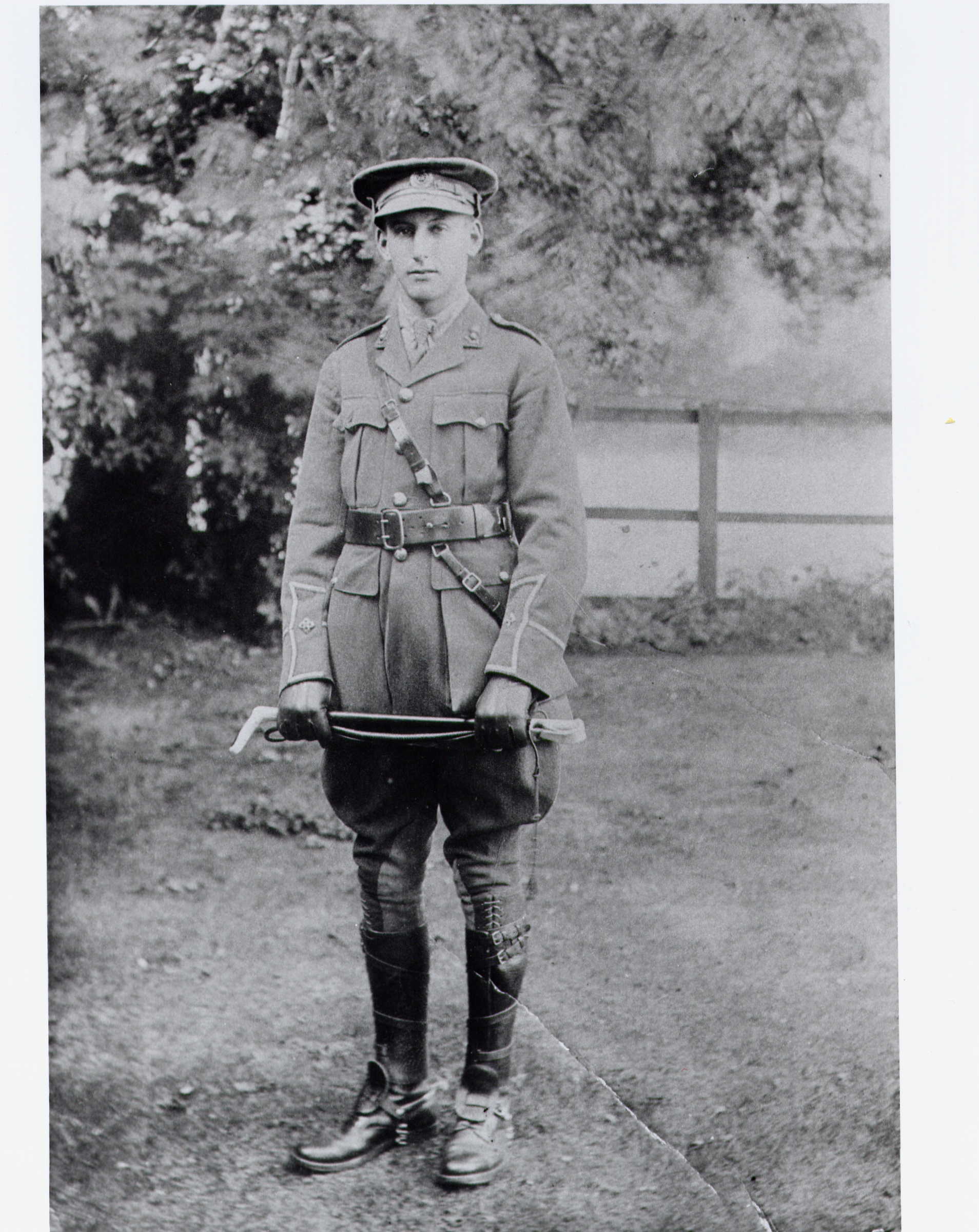
It is estimated that no less than 1600 officers from Leeds University were commissioned during the Great War. These numbers included past and present and ex-members and cadets of the university officer training corps among the staff and lecturers who also served. More than 290 officers and other ranks are known to have been killed or died of the 328 names listed on the memorial panels. Many more were wounded or injured and more than 290 military honours were awarded in total – including one VC. Captain David Philip Hirsch was awarded the Victoria Cross (Posthumous) for his part in the fighting when serving with the 4th Yorkshire Regiment in April 1917. D.P. Hirsch had joined the Leeds University OTC as an extra-mural cadet in December 1914 and was commissioned four months later.

Military communications during World War One

A pigeon being released from a port-hole in the side of a tank, near Albert in August 1918. IWM Q9247.

A pigeon being released from a port-hole in the side of a tank, near Albert in August 1918. IWM Q9247. Image licensed via IWM Non-Commercial Creative Commons license.

Military communications during World War evolved to meet new battlefield and military challenges during this period. Battles were won and lost on the strength of an army’s ability to communicate on the battlefield.  New and old systems of communications were used side by side.

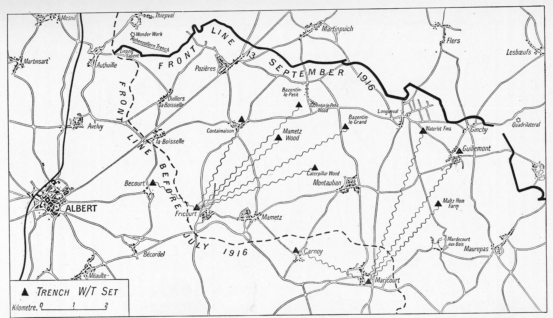
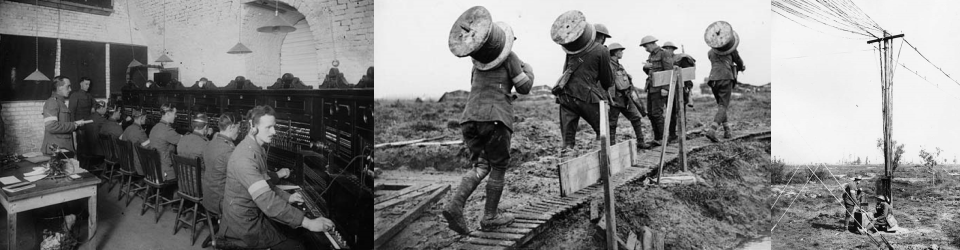
On the Western Front, the British Army used telegraph cables and telephones to communicate between the front line soldiers and commanders.  But heavy artillery (gun) bombardment meant these lines of communications were easily broken.  These lines of communications were also easily intercepted by the German army, as were the very basic wireless telegraph sets used by the British Army.  Despite this, the speed of telephone and telegraph communication meant they were the most commonly used telecommunications systems used by the British Army.

However, other systems of communications were also needed to be used in parallel with and as a backup to telegraph and telephones.  The British Army was forced to adapt, using older forms of communication such as carrier pigeons and written messages delivered by runners and messenger dogs to keep the lines of communications open.  Messenger runners had one of the most dangerous jobs in the war having to run across open ground and risk being shot by snipers in order to make sure a message was delivered.  Signalling flags were also used but could be only used in the daytime and were easily visible to the enemy.

Morse code during World War One

Signalling: a transmitting station; a receiving station, University of Leeds OTC, c.1915.

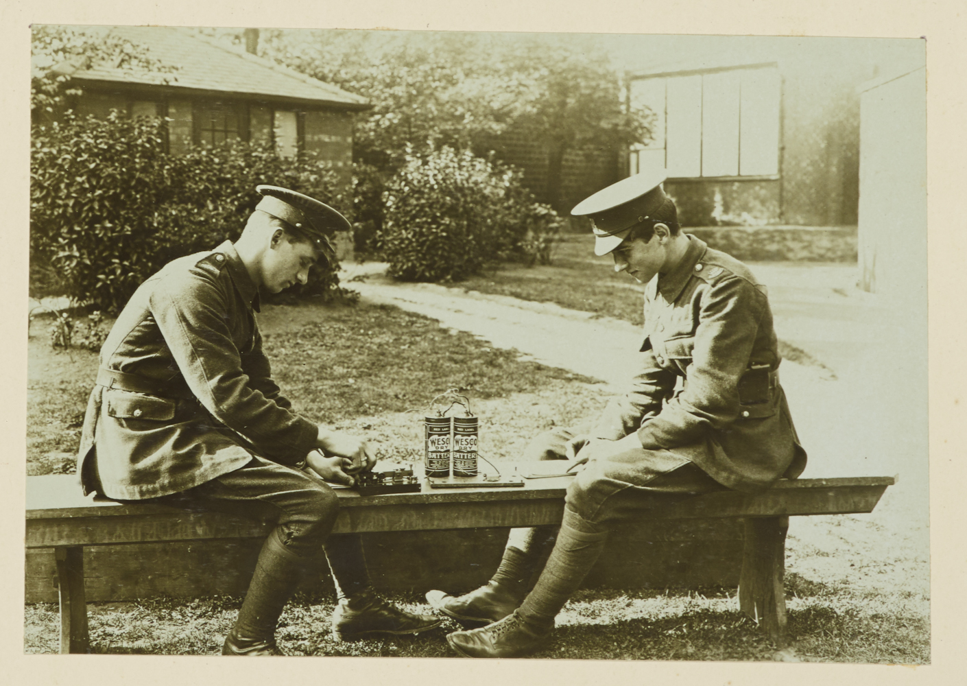
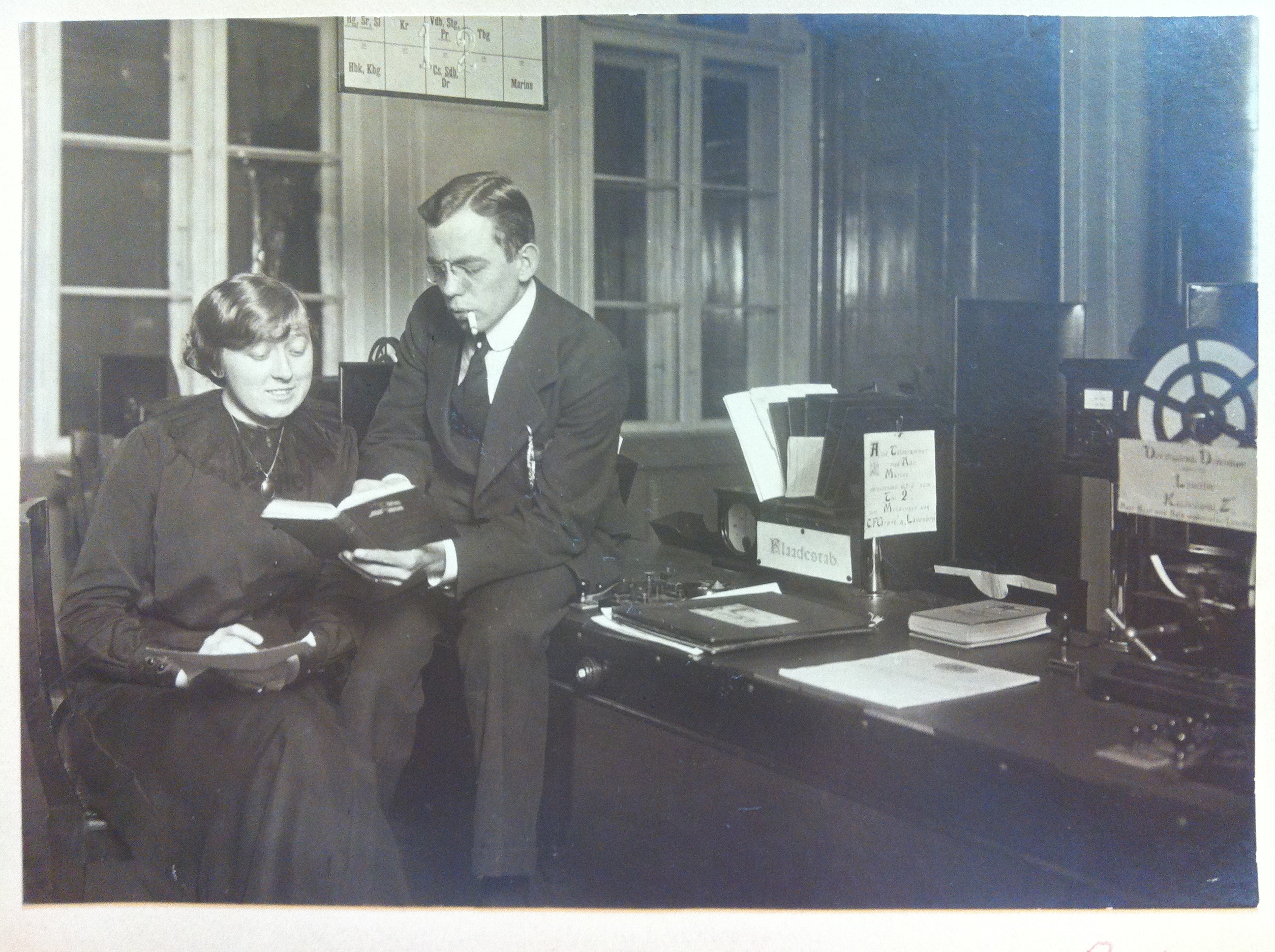
Signalling: a transmitting station; a receiving station, University of Leeds OTC, c.1915.  Image courtesy of University of Leeds Special Collections and used with permission.

This photograph shows two young officers being trained in the use of a Morse code.  It is impossible to tell from the photograph whether they are using wireless telegraphy, ordinary telegraphy or the use of the buzzer telephone but all three used Morse code during the war.

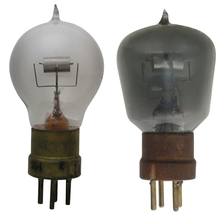
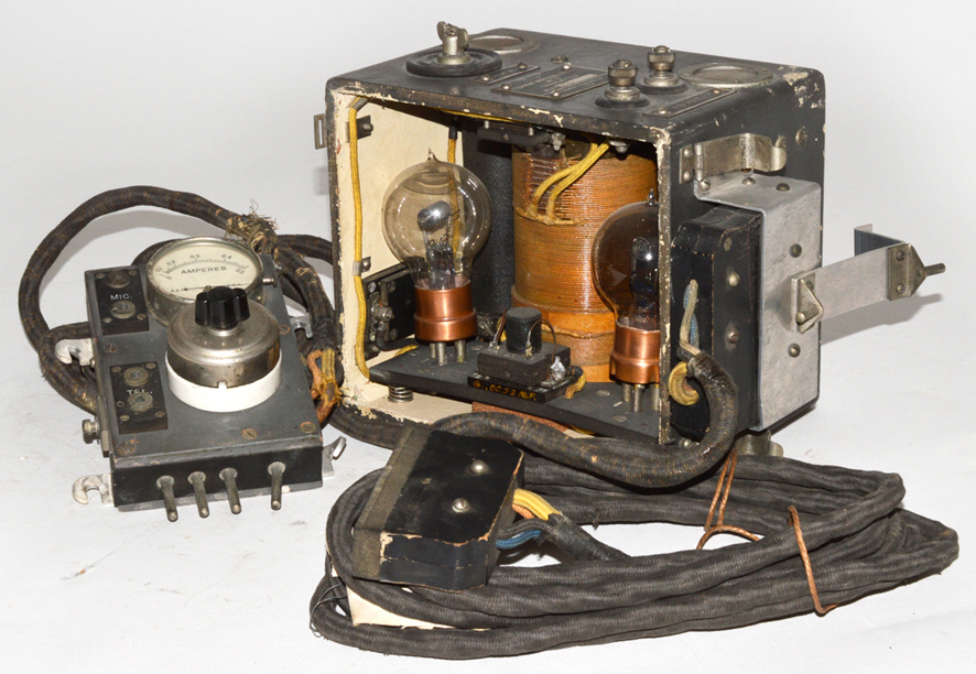
Wireless telegraph sets were used by soldiers in the trenches to communicate with generals in headquarters.  Wireless sets were useful when telephone wires were broken but could be easily listened in to or intercepted by the enemy.  Wireless sets were also heavy and could be unreliable and soldiers needed to know Morse code to send messages.

These were also problems for Royal Flying Corps pilots when they began to use wireless sets early in the war.  In 1915, Royal Flying Corps pilots began to experiment with wireless to tell soldiers where to aim their large artillery guns. However, it was still a new technology and was difficult to use while flying an aeroplane.  As with use in the trenches, wireless messages could also be intercepted by the enemy.

Morse code continued to be used as an international standard for maritime distress until 1999 but had been discontinued by many navies prior to this.  When the French Navy ceased using Morse code on 31 January 31 1997, their final message was “Calling all. This is our last cry before our eternal silence.”

Flag signalling during World War One

Signalling: a signalling parade, University of Leeds OTC, c.1915

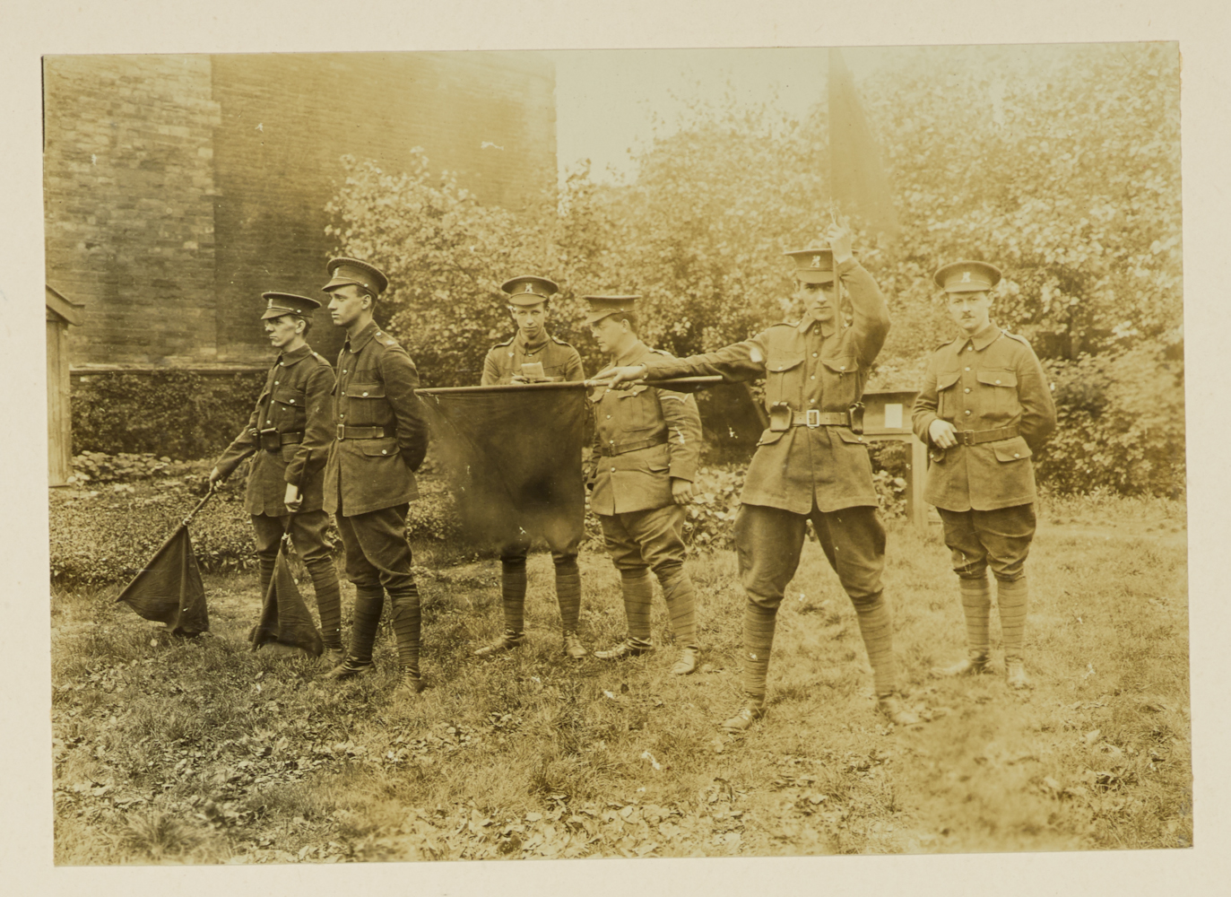
Signalling: a signalling parade, University of Leeds OTC, c.1915. Image courtesy of University of Leeds Special Collections and used with permission.

Alongside modern electrical apparatus, other, older methods of communications continued to be used throughout World War One and beyond.  Visual methods of signalling included Begbie lamps (a paraffin-burning lamp which could be used over relatively long distances), trench signalling lamps, heliographs, and flag signalling.

Flag signalling was used on land as well on sea and was usually referred to as “semaphore” when used at sea.  In both cases, fabric flags were used and, in the case of flag signalling on land, blue and white flags were usually used.  In the case of lightweight silk flags, a competent operator could reach about 12 words per minute,were used to send the fastest messages.

Flags were portable but needed good visibility and daylight.  Semaphore flags used a form of signalling based on Morse code and required a trained signaller and a trained receiver, with a telescope, pencil and notepad, at either end.

Signalling: a signalling demonstration, University of Leeds OTC, c.1915

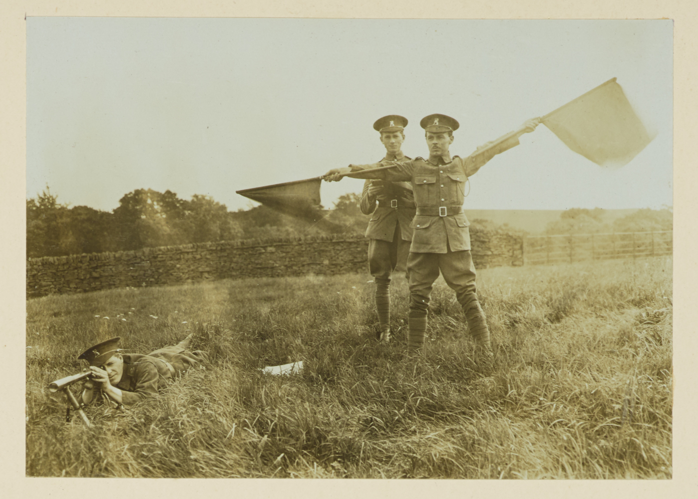
Signalling: a signalling demonstration including the use of telescope to receive signals, University of Leeds OTC, c.1915. Image courtesy of University of Leeds Special Collections and used with permission.

Signallers were regularly employed in forward positions to assist with artillery spotting and provide to information about their targets. In these often-isolated positions, signallers were often vulnerable to enemy shelling and attack and, as a result, many signallers lost their lives.

Visual signalling were quicker than sending a messenger but were easily intercepted by the enemy and could only be used over short distances.  As a result, flag signalling fell out of use in conflict communications by 1916.

For further details of flag signalling in the British Army, see The Royal Signals .. Signalling with Flags.

Images

These photographs were supplied to Legacies of War by Joanne Fitton, Special Collections Manager at the University of Leeds, and are used with kind permission.

These images are from material in the University Archive at the University of Leeds.  The University Archive was set up in 1977 to preserve the records of the University of Leeds and its predecessor bodies the Yorkshire College of Science, Yorkshire College, and Leeds Medical School, from 1874 to the present day.  The archivist actively collects material, preserving the memory of the institution, providing the evidence base for its activity and making its records accessible to researchers.

The University of Leeds also holds the Lidde Collection which includes the personal papers of well over 4,000 people who lived through the First World War, and approximately 500 who experienced the Second World War.

Sources and further information

For further information, see the Leeds University OTC tribute video put together from original historic and archive material by Legacies of War‘s Dave Stowe.  Dave has collected a number of images and press cuttings linked to his research into the Brotherton Library’s War Memorial at the University of Leeds.

The University of Leeds OTC and Roll of Honour by Dave Stowe via Western Front Association

The O. T. C. and the great war (1915) by Captain Alan R. Haig-Brown

University Archive at the University of Leeds

Liddle Collection at the University of Leeds

Royal Signals Museum: World War 1&2 Communications

The Royal Signals .. Signalling with Flags

Worcestershire Regiment: A Signaller in World War 1

About the author: Dr Elizabeth Bruton is postdoctoral researcher for “Innovating in Combat”. See her Academia.edu profile for further details.

British Army and Royal Engineers rates of pay, 1914-1915

Royal Engineers Cap Badge, as of 1900

Royal Engineers Cap Badge, as of 1900. Image available in the public domain via Wikimedia Commons.

The wonderful blog The Long, Long Trail: The British Army in the Great War of 1914-1918 has posted an article on British Army minimum daily rates of pay in 1914 and 1915, as defined by War Office Instruction 166 (1914). These rates were later revised in December 1915.

Daily rates of pay are divided into Officers and Warrant Officers, NCOs and men and are divided according to Corps.

In both categories – Offices and Warrant Officers, NCOs and men – the Royal Engineers (which then incorporated the Signals Service) were amongst the best paid men in the British Army in 1914 and 1915, particularly at the more junior officer rank levels. Officers in the Royal Engineers shared the same basic minimum daily rate of pay as other corps but were awarded “Engineers Pay” which was an additional payment of between 20-50% of their baseline pay. In addition to their basic pay and additional “Engineers Pay”, Second Lieutenants could be awarded a further 1s 6d if they were certified by their Commanding Officer as to their technical efficiency.

Table of Officers’ daily rates of pay by rank and by corps (excluding the Royal Flying Corps)

These are the minimum daily rates of pay for typical ranks or appointments of all arms. All rates in Shillings (s) and Pence (d).

Cavalry of the Line, Irish Horse, King Edward’s Horse and Yeomanry Royal Horse Artillery Royal Field Artillery and Mountain Artillery Royal Garrison Artillerya Royal Engineersb Infantry Army Service Corpsc Royal Army Medical Corps Army Veterinary Corps
Lieutenant-Colonel 29s 6d 29s 9d 28s 0d 29s 6d
24s 6d
35s 0d
21s 0d
28s 0d 27s 0d
21s 0d
30s 0d 30s 0d
Major 17s 0d 18s 6d 16s 0d 19s 6d
16s 0d
25s 0d
16s 0d
16s 0d 19s 0d
15s 0d
23s 6d 20s 0d
Captain 13s 6d 15s 0d 13s 6d 15s 6d
13s 6d
17s 6d
13s 6d
12s 6d 15s 6d
12s 6d
15s 6d 15s 6d
Lieutenant 9s 6d 10s 6d 9s 6d 10s 6d
9s 6d
12s 6d
9s 6d
8s 6d 11s 6d
8s 6d
24s 0dd
14s 0d
13s 8d
Second Lieutenant 8s 6d 9s 6d 8s 6d 9s 6d
8s 6d
11s 0d
9s 6d
8s 6d
7s 6d 10s 6d
7s 6d
N/A 11s 6d
Quartermaster 11s 6d 11s 6d 10s 6d 10s 6d
10s 6d
12s 6d
10s 6d
10s 0d 10s 6d
10s 6d
10s 6d 30s 0d

a The figure in bold for the Royal Garrison Artillery includes Armament Pay which was payable only if certified by Commanding Officer with regard to the Second Lieutenant’s technical efficiency.

b The figure in bold for the Royal Engineers includes Engineer Pay and in the case of the Second Lieutenant the higher figure in bold and italics also includes a further 1s 6d payable only if certified by Commanding Officer with regard to the Second Lieutenant’s technical efficiency.

c The figure in bold for the Army Service Corps includes Corps Pay

d Temporary Lieutenants in the Royal Army Medical Corps serving under civil contracts receive 24s 0d per day

As can be seen by this table above, the Royal Engineers’ rates of pay (marked in red) were some of the highest across the different corps and different ranks. They were comparable with those of another technical occupation, that of the Royal Flying Corps which has been omitted as their ranks do not necessarily map readily onto those of the other Army corps at this time.

The high rates of daily pay offered to the Royal Engineers and indeed to some other Army corps show the financial value and importance of technical and specialist expertise to the British Army in the early stages of the First World War. Further to this, these figures also offer a fascinating comparison of the importance and value of engineers, especially younger officers with technical expertise, in the British Army at the start of the First World War.

See British Army 1914 rates of pay for the minimum daily rates of pay for the different corps of the British Army in 1914 and 1915.

UPDATE: For an excellent overview of the Royal Engineers between 1914 and 1918, see The Long, Long Trail: The Royal Engineers of 1914-1918.

About the author: Dr Elizabeth Bruton is postdoctoral researcher for “Innovating in Combat”. See her Academia.edu profile for further details.

German cable telegraphy in World War One: Yap Island

By Elizabeth Bruton

CS Stephan off the New Guinea coast, laying the Dutch East Indies - Yap - Guam cable, c.1906

CS Stephan off the New Guinea coast, laying the Dutch East Indies – Yap – Guam cable, c.1906. Image available in the public domain via Atlantic-cable.com.

Located in the western Pacific Ocean and forming part of the Caroline Islands, Yap Island was a major German naval communications centre in the early twentieth century up to World War One and was an important international hub for cable telegraphy.

From the seventeenth century up to 1899, Yap Island was a Spanish colony within the Captaincy General of the Philippines. After the defeat against the US in 1898 and subsequent loss of the Philippines, Spain sold these islands and its other minor Pacific possessions to Germany.

In the early twentieth century, the Deutsch-Niederlandische Telegraphen-gesellschaft (German-Netherlands Telegraph Company, sometimes translated as German-Dutch Telegraph Company) was established with the remit to link the German Pacific Colonies into the main submarine telegraph networks.  As part of this, in 1906 the company laid telegraph cables from Menado, Dutch East Indies to Yap Island and to Guam.  At Yap Island, a spur was run into Shanghai.  Yap Island formed part of the Menado-Yap-Guam-Shanghai undersea cable route and this route meant that Germany was no longer reliant on British-controlled (“All Red”) telegraph cables in the Pacific.

German-Netherlands Telegraph Company District Office and Cable Station, Yap.

German-Netherlands Telegraph Company District Office and Cable Station, Yap. CS Stephan is at centre right. Dated 2 July 1908, the card was sent to a member of the staff of the German Atlantic Telegraph Company Cable Station at Vigo, Spain. Image available in the public domain via Atlantic-Cable.com.

Between 1906 and 1914, Yap became a major German naval communications centre and was an important international hub for cable telegraphy as it offered one of the two key alternative routes to the US-controlled Commercial Pacific cable. Yap Island formed a key node in the German telegraph cable line which also included Guam, Shanghai, the Dutch East Indies, and the Philippines.  Some telegraph messages sent to the German South Sea domain were delivered on from Yap by ship and, after the construction of a wireless station around 1910, by wireless.

Around 1910, the German South Sea Radio Company (a subsidiary company of the German-Netherlands Telegraph Company) established a wireless station on Yap Island to provide wireless communication where a telegraph cable would have been costly and difficult to lay: to Rabaul in New Guinea and to Nauru.  The station, issued the callsign KJA, had a range of 300-500 miles and was commercially operated.

Upon the outbreak of war in early August 1914, Yap Island as well as its telegraph station came under the mandate of Japan.  The wireless station was destroyed by British naval cruisers shortly after war broke out on 12 August 1914 and the Japanese shut down the telegraph station for the duration of the conflict.  The Japanese mandate continued for a short period after the end of the war and this was confirmed by the Treaty of Versailles in 1919.

However, this tiny island in the middle of the Pacific was of immense strategic importance in the overall global telegraph cable network and was one of only two alternative routes to the US-controlled Commercial Pacific cable from Manila to San Francisco; the other alternative route passed through Japan.

The US was deeply concerned about control of the Pacific Ocean and competition with Japan, both in terms of shipping lanes as well as the telegraph cable network.  As a result, the US objected to Japanese control over the island.  This was eventually rectified by an agreement signed in December 1921 and which came into effect in 1922 which recognised the Japanese mandate over the island of Yap but gave the US equal access to the island and shared control, management, and operation with the Japanese of the telegraph station and the cable from Yap to Guam. The Japanese fortified the island and continued to control the island until it was occupied by the US towards the end of World War Two.

Jetty & buildings on Yap Islands, probably dating from German colonial period

Jetty & buildings on Yap Islands, probably dating from German colonial period. With narrow-gauge tramway tracks running down the jetty. Image available in the public domain via Spontoon Island: Pacific Island Architecture.

Sources

Wrinkler, Jonathan Reed. Nexus: Strategic Communications and American Security in World War I (2008).

Memorandum on Cable Communications in the Pacific.Memorandum (Institute of Pacific Relations, American Council), Vol. 1, No. 16 (Sep. 1, 1932), pp. 1-3.

Knoll, Arthur J. and Hermann J. Hiery (eds). The German Colonial Experience: Select Documents on German Rule in Africa, China, and the Pacific 1884-1914 (2010).

The World at War: CAROLINE ISLANDS 1898 – 1919

History of Yap by William Hampton Adams

History of the Atlantic Cable & Undersea Communications: German Cable Companies by Bill Glover

Department of the Navy and the Bureau of Steam Engineering. Wireless Telegraph Stations of the World including shore stations, merchant vessels, revenue cutters, and vessels of the US Navy, updated to 1 January 1912 (1912).

About the author: Dr Elizabeth Bruton is postdoctoral researcher for “Innovating in Combat”.  See her Academia.edu profile for further details.

Guest Post by Brian Austin: Wartime Wireless Intelligence and E.W.B. Gill

A rare image of EWB Gill, taken in 1922

A rare image of EWB Gill, taken in 1922

Walter Gill (1883 – 1959) was an Oxford physicist and a specialist in electromagnetic phenomena. He was also a man with an incisive mind – though well-balanced by a ready sense of the absurd.  A likely candidate, one would have thought when war broke out in August 1914, for some useful position in the Army then assembling with much urgency. But Gill was too old, so he was told, to be commissioned as an officer and so he took himself to the recruiting office and volunteered as a private.

Following a short spell digging trenches on the Isle of Wight, Gill received a letter from the War Office reconsidering its earlier decision. He was offered a commission in the heavy artillery – his knowledge of trigonometry had clearly helped – and told to report to Woolwich. But the arsenal had no guns so, to keep its newly-created officers busy, they were lectured on the art of grooming horses, incessantly. During the time he spent there, much of which involved such seemingly pointless activities, the not-so-young Second Lieutenant Gill became acquainted with many strange military practices not least of which was the need to salute almost anything that moved.

But the war was itself moving on and soon it was realised that there was need for officers well-versed in the wireless art and especially its use for intelligence purposes. Gill was immediately transferred to the Royal Engineers in whose parish wireless had found itself.  This appealed to him for many and obvious reasons: his physics background equipped him rather better than most for such a technical task and his natural scepticism, when confronted by extravagant claims, made him the ideal intelligence analyst.

Front cover of "War, Wireless & Wrangles" by EWB Gill (1934).

Front cover of “War, Wireless & Wrangles” by EWB Gill (1934).

After the war, in 1934 in fact, Gill published a delightful book describing his wartime experiences.  Called War, Wireless and Wangles, and illustrated with some wonderful cartoons, the book recounted, in often hilarious detail, the contest between the “Teutonic mind”, as he saw the German obsession with organisation of the most methodical and precise kind and the, at times, almost shambolic British response.  As just one example, he described how the Zeppelins, those cumbersome predecessors of the bombers of the next war, were all equipped with wireless and each had a call sign beginning, shall we say, with the letter L followed by another, thus LA, LB, LC and so on.  It took little intelligence, in both senses of the word, on the British side to soon deduce that this grouping of letters was reserved for the German Zeppelin fleet and, from that, considerable operational advantage flowed. Some time later, realising this weakness in their system, the German planners changed their call signs but, in well ordered fashion, so LA became MB and so on. More was to follow.

One of the cartoons from War, Wireless and Wrangles (1934)

One of the cartoons from War, Wireless and Wrangles (1934).

Every hour, and almost on the hour, those Zeppelins would report their position to the High Seas Fleet under whose command they fell.  These regular wireless transmissions were a bonanza of the highest order for the listening British wireless stations with their associated direction-finding facilities.  Not only was warning given of an impending attack, several hours before they crossed the British coast, but their positions and courses were plotted as they lumbered on.

But behind the humour was much of historical value too, particularly of a technical nature.  The art of direction finding by radio came into its own during the war owing to the work of two brilliant engineers at the Marconi Company: H.J. Round and C.S. Franklin. By means of the infant valve technology of the time that provided unprecedented amplification, and arrays of antennas that produced controlled directivity, these two men gave the Army a formidable intelligence tool. But it was the Royal Navy, initially highly sceptical until they changed their view on seeing the performance of that equipment when deployed in France, that took great advantage of the technology.  In May 1916, a 1.5 degree shift in a DF bearing indicated that the German High Seas Fleet was on the move from its anchorage at Wilhelmshaven and this intelligence enabled the Navy to position its Grand Fleet for the Battle of Jutland that took place the next day.

Another cartoon from War, Wireless and Wrangles (1934)

Another cartoon from War, Wireless and Wrangles (1934)

Gill himself was soon on his way to Egypt. He was posted to what would become a wireless intercept station but his first task was to assemble another one on Cyprus so he proceeded thither with the four tall masts of a Bellini-Tosi DF antenna. That they fell down during the erection process was merely part of the Army’s day but all was soon well once the guys had been correctly set. By now Gill had become something of an antenna expert and his next contribution followed in short order. Back in Egypt and charged with setting up another intercept station he astounded his commanding officer when he announced that he’d found the ideal very tall supporting structure for its aerial. Since nature had provided nothing taller than palm trees in the region, the CO was naturally sceptical until Gill pointed out the Great Pyramid at Giza with a wire affixed to its pinnacle.  This aerial proved itself to be very effective: a Zeppelin, on its mission over England, was heard on the single-valve receiver of the station. No mean feat!

After encounters with Egyptian princes and British Army officers who kept pet chameleons, Gill began to acclimatise to the rather exotic way of life common, or so it seemed, at the eastern end of the Mediterranean.  From Cyprus he went to Salonika to take charge of one of the intelligence wireless stations in that region. This was the place, it was alleged, that St Paul only visited once. Afterwards he contented himself by writing epistles to its inhabitants.  It turned out that malaria was rife in the country and, as might be expected, the Army took this very seriously. Various deterrents were either to be swallowed or applied as medical science evolved. One day he noted that the latest approved substance bore an uncanny resemblance to gearbox grease. It was claimed to be lethal to mosquitoes. However, Gill was confronted by the regimental sergeant major just before he was due to order all his men apply the stuff to themselves. Should he first remove the mosquitoes from the tin where they appeared to be eating the grease?

Another cartoon from War, Wireless and Wrangles (1934)

Another cartoon from War, Wireless and Wrangles (1934)

By the war’s end, the now Major Gill had become one of the British Army’s experts in the art of wireless intelligence both technically and operationally. The latter skill he acquired without benefit of formal instruction. When in Egypt, and the flow of intercepted German wireless traffic became a daily occurrence, the standard procedure was to send it all, by cable, to London where it would be deciphered by experts, perhaps at “Room 40” the centre where such dark arts were practised. But to a man of Gill’s intelligence and curiosity, and with the collaboration of a similarly endowed colleague, it seemed only natural to “have a go” themselves. And soon, based on little more than common sense plus the application of a logical mind, they did indeed “crack” the code. It should be said at this stage that it was by no means a high-grade cipher; more like something based on a “child’s first cipher-book”, as Gill put it. German cipher policy, it would seem, differentiated between theatres of war and clearly the further east those happened to be the lower the quality of the cipher required.

They duly sent the deciphered ciphers to London in the approved way and fully expected to be soundly reprimanded for their unauthorised efforts. However, the reaction forthcoming was precisely the opposite: their action was approved and the War Office said they would send one of their experts to Egypt to give Gill and his colleague instruction in the latest cipher-solving devices. This story has interesting repercussions soon after the outbreak of the next World War when, once again, Gill offered his services to the military. And again he found himself at the very sharp end of the intelligence war. However, this time, his indiscretion by once again breaking the German code (emanating from the Abwehr no less) had a very different outcome. That story, though, has been told elsewhere and will not intrude upon this account of his First World War service.

Walter Gill’s war ended in 1918 with him back in England and in command of the Army’s intelligence wireless stations as well as a training school. For his service he was awarded the OBE (mil.) and was twice mentioned in despatches. One of Gill’s many remarkable characteristics was his modesty. He sought no honour for himself nor even any publicity. Finding a single photograph of the man proved a major task and when accomplished it shows Walter Gill, back at Merton College, Oxford, in 1922 where he resumed his academic career until the next encounter with the Germans when he again offered his services.

This blog post is based on Dr Austin’s full-length article on EWB Gill published in The Journal of the Royal Signals Institution vol.29, No.2, Winter 2010 [pdf].

About the author

Dr Brian Austin is a retired engineering academic from the University of Liverpool’s Department of Electrical Engineering and Electronics. Before that he spent some years on the academic staff of his alma mater, the University of the Witwatersrand in Johannesburg, South Africa. He also had a spell, a decade in fact, in industry where he led the team that developed an underground radio system for use in South Africa’s very deep gold mines.

He also has a great interest in the history of his subject and especially the military applications of radio and electronics. This has seen him publish a number of articles on topics from the first use of wireless in warfare during the Boer War (1899 – 1902) and South Africa’s wartime radar in WW2, to others dealing with the communications problems during the Battle of Arnhem and, most recently, on wireless in the trenches in WW1. He is also the author of the biography of Sir Basil Schonland, the South African pioneer in the study of lightning, scientific adviser to Field Marshall Mongomery’s 21 Army Group and director of the Atomic Energy Research Establishment at Harwell.

Brian Austin lives on the Wirral.

Guest post by Keith Thrower: Army radio communication in the Great War

Prior to the outbreak of WW1 in August 1914 many of the techniques to be used in later years for radio communications had already been invented, although most were still at an early stage of practical application. Radio transmitters were predominantly using spark discharge from a high-voltage induction coil. The transmitted signal was noisy and rich in harmonics and spread widely over the radio spectrum.

The ideal transmission was a continuous wave (CW) and there were three ways of producing these: by an HF alternator, a Poulsen arc generator or a valve oscillator. The first two of these were high-power generators and not suitable for battlefield communication. Valve oscillators were eventually universally adopted. Several important circuits using valves had been produced by 1914. Predominant amongst these were the amplifier, detector and oscillator. The oscillator, apart from its use as a CW generator for radio transmitters, was also used in radio receivers in a heterodyne circuit and the resulting beat note produced an audible tone of the Morse signal in the headphones.

Valves at this time were still at a primitive state of development. Those available were: The Fleming diode, the de Forest audion triode and the C and T triodes designed by the Marconi engineer Henry Round. All these triode valves were gas-filled to improve their sensitivity but had erratic performance.

Both the C and T valves were used in the Marconi Short Distance Wireless Telephone Transmitter and Receiver. This radio, however, would not have been robust enough for use under battlefield conditions. The C valve, however, was used by the army in direction finding stations.

Early army radios

At the start of the war the only radios available were a few 500-watt and 1500-watt spark transmitters and their crystal-detector receivers. The 500-watt pack sets were used with Cavalry Brigades and the 1500-watt wagon sets with Cavalry Divisional Headquarters and General Headquarters.

The principal method of communication by the British army, up to late 1917, was by cable for speech and Morse transmission. Initially, a single cable was laid above ground and the earth used as the return. However, the cable was vulnerable to damage by enemy fire and by the passage of tanks across the battlefield, a problem not solved even when buried cable was used. Very often communication was not possible, particularly when troops were moving rapidly forward or in retreat. During the course of the war tens of thousand miles of cable was laid and, at times, there was an acute shortage of replacement cable.

It was found that the Germans were able to listen in by picking up earth currents or tapping into the cable. This was not realized at first but, when discovered, it was necessary to limit the number and content of the message and, where possible, to use codes or encryption. A solution to this was the Fullerphone, which made the signal immune from eavesdropping, but it could not be used for telephony.

Other non-wireless means of sending messages that were used with mixed success during the war was by runners, dispatch riders, pigeons, lamps and flags.

Up until the end of March 1918 the Royal Flying Corp was part of the army and experimental work on aircraft radio communication was carried out at Brooklands and later at Biggin Hill. The development group, headed by Major Charles Prince, also worked on the development of CW voice transmission. This culminated in mid-1916 with the successful demonstration of ground-to-air speech communication. However, it was to be a further two years before suitable equipment was incorporated in aircraft. Consequently all the early radios were spark transmitters fitted in the aeroplanes and crystal receivers on the ground.

No 1 Aircraft Spark

Amongst the earliest radios to be used in aeroplanes was the 30‑watt, No 1 Aircraft Spark (Figure 1), powered from an accumulator. The set was designed in 1914 and fitted to approximately 600 aircraft during 1915. It was used for spotting enemy artillery and reporting back to ground by Morse code. There were several variants of the set and, altogether, nearly 4000 of these were manufactured.

Unlike with the RFC there was a general lack of enthusiasm in the army for using radios, particularly during the first two years of the war. There were several reasons for this: the equipment was bulky; the accumulators needed frequent re-charging; and there was a genuine fear that the enemy would be able to intercept the messages.

This situation was to change later in the war when radio had proved to be the only reliable way to communicate, particularly when troops were on the move.

The BF Trench Set

One of the earliest radios to be used in the trenches was the 50-watt Trench Set, also known as the BF Set (Figure 2) which was used for communication from Brigade to Division. This went into action in the Battle of Loos in September 1915 and in the first Battle of the Somme on July 1st 1916. The transmitting portion of set was based on the design of the No 1 Aircraft Spark set. The receiving portion used a carborundum crystal detector. It was powered from an accumulator and also required dry-cell batteries for biasing the carborundum crystal and an internal test buzzer.

Its range was 3.7km with aerials mounted on masts but this reduced to 1.1km when the aerial was run close to the ground.

Careful planning of frequencies was required in order to minimize interference from neighbouring spark transmitters, a problem much simplified when CW sets came into use.

The BF set was used extensively during the second half of the war and approximately 1200 were manufactured.

130-watt Wilson Trench Set & Short Wave Tuner Mk. III

The Wilson Transmitter was used primarily for Division to Corps communication and Corps Directing Station. This set came into service about the same time as the BF Trench Set. It had a fixed spark gap with a motor-driven, high-speed interrupter rather than the slower magnetic interrupter. The greater number of sparks produced a musical note in the headphones, making the Morse signal more easy to hear through interference. The transmitter had the same frequencies as the BF set and the higher power meant that the range was up to 8.3km. The set was supplied by an accumulator.

Tuner Short Wave Mk. III*

The Mk. III version of this tuner was introduced in 1916 and the Mk. III* in 1918. Its prime purpose was to receive Morse messages from aircraft flying over the trenches but it was also used with the Wilson Set. The receiver used a crystal detector and there was a buzzer for calibrating and testing the tuner. Total production was 766 transmitters and 6595 receivers.

Later valve Developments

Towards the end of 1915 an entirely new type of valve was developed under Colonel (later General) Gustav Ferrié who was in charge of the French Military Telegraphic Service. The construction was very simple: it had a straight tungsten filament, a spiral grid and a cylindrical anode. It was evacuated to a low pressure and during the manufacturing process the glass and metal parts were heated to a sufficient temperature to release occluded gases. The valve, known as the TM, was immensely successful and widely used throughout the war, over 100,000 of which were made by the two French companies, Fotos and Métal. By 1916 it was being manufactured in Britain as the R-valve.

There were many variants, including the Air Force C and D, and the low-power transmitting valves B, F and AT25. Two higher power transmitting valves, introduced in late 1917, were the T2A and T2B which had 250 watt dissipations. These were used by the RFC (later RAF) in ground station CW transmitters.

One problem with the TM and R-valve was the high capacitance between the anode and grid. This made its use as an RF amplifier very difficult because energy fed back from the output of the valve to its input was liable to cause unwanted oscillation.

To overcome this Round of the Marconi Company developed the type Q in 1916 which featured small size and low capacitance. It had a straight tungsten filament terminated by the two pointed metal caps at each bend of the bulb. Both the anode and grid connections were taken to two further caps near one end of the tubular glass bulb. The Q was primarily intended as a detector but it was also used as both an amplifier. It overall length was 73mm and the bulb diameter 16mm. Later in the war Round designed the V24 which was better suited as an RF or AF amplifier.

Later army radios

Valve radios first made their appearance in 1916. One of the earliest was the Tuner Aircraft Valve Mk. I but this was not made in significant numbers.

W/T Set Forward Spark 20 watt “B”

This set came into service in 1917 and was also known as ‘The Loop Set’ and was used for forward communication. There were both Rear Stations and Front Stations sets, with two versions of each. There were also separate receivers for the Rear and Forward Stations. These receivers had two valves which were either the French TM or the British R.

The transmitter had a fixed spark gap powered directly from an induction coil operating in a similar way to the BF Trench Set. The power for the stations was supplied by an accumulator and a 32-volt HT battery.

Approximately 4000 of the transmitters and receivers were manufactured.

W/T Trench Set Mk. I 30-watt

The first CW sets for field use were made in 1916 and used a single valve for both the transmitter and receiver circuits and was used for forward communication by ICW. The Mark 1* version came into service in 1917 and incorporated a high-speed interrupter to modulate the transmission.

W/T Set Trench CW Mk. III*

This (CW) set comprised a transmitter and a heterodyne receiver in separate boxes. It came into service in 1917 and was used for forward area telegraphy.

The transmitter was rated at 30-watts and had a range of 3.7km. It utilised two valves which were either the type B or AT25.

The receiver had two R valves. The first of these was used in a heterodyne circuit and the second as an audio frequency amplifier for the Morse signal.

The complete set also included a heterodyne wavemeter, Selector Unit and Rectifier Unit.

Total production was a little under 3000 for both the transmitter and the receiver and approximately 400 of the Selector Units.

Telephone Wireless Aircraft Mk. II

The Telephone Aircraft Mk. II came into service in 1917. It had two B or F valves, one being used for control and other an output valve. An accumulator was used to supply the valve’s filaments and the HT was derived from a wind-driven generator. It had a range of 3.2km to other aircraft and 2km to ground stations.

The aerial was a trailing wire of length 100–150ft with a lead weight at the end.

Earlier attempts to fit radio telephones in aircraft had been hampered by the high background noise from the aircraft’s engine. This problem was alleviated by the design of a helmet with built-in microphone and earphones to block much of the noise.

A typical receiver for use with this transmitter was the Tuner Aircraft Mk III which had three R valves, one for the detector and two for low-frequency amplification.

Conclusions

The army was very slow to adopt wireless for communication on the battlefield and relied too much on communication by cable. There was a genuine fear that wireless would be intercepted by the enemy but this was also true with cable. The cable used was being constantly severed by shell fire and the passage of tanks across the battlefield.

Apart from a few high-powered transmitters that played a minor role in the war, the first wireless transmitters were fitted in aircraft during 1915. These were used to communicate with crystal receivers on the ground to direct artillery fire.

The first trench sets went into service towards the end of 1915. From this time onward the army came slowly round to realizing that wireless communication was a more reliable way to communicate than by cable, particularly when troops were moving rapidly forwards or backwards.

The most significant technical breakthrough came following the development of the TM valve in France. This, and its many derivatives, enabled reliable valve transmitters and receivers to be produced from 1916 onwards. It now became possible to make CW transmitters, which were far superior to the spark sets.

By mid-1917 the army at last accepted that radios were the best way to communicate and increasing numbers of these came into service in the final year of the war.

Acknowledgements

I should like to thank Nick Kendall-Carpenter and his archive staff at the Royal Signal Museum, Blandford, Louis Meulstree and John Liffen of the Science Museum for their valuable assistance.

About the Author: Keith Thrower OBE is author of British Radio Valves: The Vintage Years – 1904-1925 and British Radio Valves: The Classic Years 1926-1946.

This article is based on the paper Keith gave at “Making Telecommunications in the First World War” in Oxford on 24 January 2014. See our events page for full details including the abstract, PowerPoint slides and full version of Keith’s paper.

(left) Commercial version of Fleming diode; (right) BT-H version of the de Forest Audion triode

Fig. 1 (left) Commercial version of Fleming diode; (right) BT-H version of the de Forest Audion triode, a ‘soft’ valve erratic in operation.

Marconi-Round C and T valves of 1913

Fig. 2: Marconi-Round C and T valves of 1913. These were both ‘soft’ valves. The C was a receiver valve for use as a detector or RF amplifier. The T was a transmitter valve.

Marconi Short Distance Wireless Telephone Transmitter and Receiver

Fig 3: Marconi Short Distance Wireless Telephone Transmitter and Receiver. This set used a C valve in the receiver, connected as an RF amplifier with regenerative feedback to increase its gain and provide improved selectivity. Detection was by a carborundum crystal. For transmission there was a single T.N. valve (seen mounted in the frame) and this was connected as an oscillator. It is believed that Marconi used this set for CW voice trials in 1914.

Marconi 1.5 kW spark generator of approx. 1911 design

Fig 4: Marconi 1.5 kW spark generator of approx. 1911 design. Note the rotating spark gap seen at the front.

Marconi 1.5 kW spark Pack Set

Fig 5: Marconi 1.5 kW spark Pack Set showing the operating cart with the crystal set receiver.

No. 1 Aircraft Transmitter Spark

Fig 6: No. 1 Aircraft Transmitter Spark. 30-watt input. Note the spark gap on the top right inside the cabinet with the adjustment for the gap at the front.

W/T Trench Set 50 Watt D.C. (Also known as the BF set)

Fig 7: W/T Trench Set 50 Watt D.C. (Also known as the BF set) The spark gap is clearly seen at the bottom.

W/T trench Set 130-watt Wilson

Fig 8: W/T trench Set 130-watt Wilson. Transmitter only; used with Tuner Short Wave Mk. III.

Tuner Short Wave Mk. III*

Fig 9: Tuner Short Wave Mk. III*. This receiver has both a carborundum and a Perikon detector.

French TM and Osram F valve

Fig. 10a & 10b: French TM and Osram F valve. The TM was a general-purpose valve used mainly as a detector or an AF amplifier. The F was a low-power transmitting valve similar in construction to the TM.

Top Q, bottom V24

Fig. 10c & 10d: Top Q, bottom V24. The Q went into production at Edison Swan in 1916 and was used mainly as a detector. The V24 probably went into production at the end of 1917 or early in 1918. It was used as both an RF and an AF amplifier.

W/T Forward Spark 20-watt “B” transmitter

Fig. 11: W/T Forward Spark 20-watt “B” transmitter.

Fig. 12: W/T Forward Spark 20-watt “B” receiver.

Fig. 12: W/T Forward Spark 20-watt “B” receiver.

W/T Trench Set Mk. I

Fig 13: W/T Trench Set Mk. I. Combined transmitter & receiver.

W/T Receiver Short Wave Mk. III**

Fig 14: W/T Receiver Short Wave Mk. III**.

W/T Trench Set Mk III* transmitter

Fig 15: W/T Trench Set Mk III* transmitter.

W/T Trench Set Mk III* receiver

Fig 16: W/T Trench Set Mk III* receiver.

Tuner Aircraft No. 9

Fig. 17: Tuner Aircraft No. 9. This went into service in 1916.

Telephone Wireless Aircraft Mk. II

Fig 18: Telephone Wireless Aircraft Mk. II, complete with remote control and headphones.

Guest post by Andreas Marklund: Female Censors at the Danish State Telegraph during World War One

Two young telegraphers at the Main Telegraph Station in Copenhagen c.1915

Two young telegraphers at the Main Telegraph Station in Copenhagen, Miss Galschiøtt and Mr. Henriksen, aiding a secret military intelligence unit called Kystcentralen, circa 1915. Post & Tele Museum, Copenhagen.

On June 1, 1918, ten “ladies” with “excellent language skills” had their first day of work as telegram censors at the Danish state telegraph. They had all been tested in foreign languages – German, French and English – by a professor at the University of Copenhagen, and all of them were quite literally daughters of the elite. The first two names on the list of employees are illuminating: “Miss INGER GRAM, daughter of the Supreme Court President, Dr. Jur. R.S. Gram”, followed by “Miss ASTRID HERTZ, daughter of the Medical Officer, Dr. Med. Poul Hertz.”

Inger Gram and Astrid Hertz, and their eight, equally unmarried colleagues, were employed by the Danish Ministry of Foreign Affairs but their office was located at the Main Telegraph Station in Copenhagen. Here, the Ministry of Foreign Affairs had a unit for cable censorship, which had been in operation since November 1916. In fact, the system of censorship and secret monitoring had been up and running since August 1, 1914, when the Telegraph Directory decreed that no telegrams transmitted from Denmark should contain “sensational and false messages about Danish conditions and popular moods“. However, the system was loosely organized in the beginning of the war, and the Ministry of Foreign Affairs was anything but satisfied with the practical handling of censorship issues, which initially sorted under the Telegraph Directory and the so-called Ministry for Public Works. Accordingly, after a harsh debate in the Danish parliament, the Ministry of Foreign Affairs took charge of the surveillance system and established its own Censorship Office at the Main Telegraph Station, which was staffed by four external censors who had no previous connections to the Danish State Telegraph.

Yet the system remained inefficient and defective. The Ministry of Foreign Affair’s censorship director, Marinus Yde, complained in a memo to his superiors that merely 500-600 telegrams, out of the approximately 7 000 telegrams that the Danish State Telegraph transmitted on a daily basis, were handed over to his censors. Thus, there was clear lack of cooperation between the censors and the ordinary telegraph staff. In another memo, dated to 29 April 1918, Mr. Yde bemoaned this glitch in the system in a rather candid tone:

The whole mountain of telegram correspondence is thus being processed without any other control than that which is carried out by the (often very young) telegraph operators, while they are transmitting and charging the telegrams. This kind of control is of no value at all.

This is where Miss Inger Gram and her nine female colleagues entered the picture. They were definitely not the first women within the Danish telecommunications sector. The first female telegraph operator in the country, the famous author and feminist Mathilde Fibiger, had entered service as early as in 1863, and there had been women working for the Censorship Office before the summer of 1918, for instance as stenographers and record keepers. Yet the idea of employing women as cable censors was a novelty of World War One – and its origin was seemingly Swedish. In the above-mentioned 1918 memo, Mr Yde wrote about an excursion to the Main Telegraph Station in Stockholm, where female censor clerks functioned as a kind of basic control filter, by “sifting” the “whole mountain” of incoming and outgoing telegrams. And whenever they discovered a suspicious message, it was forwarded to senior (male) censors in a neighboring office.

Mr. Yde was greatly impressed by this model and recommended it with enthusiasm to his superiors. The gender aspect was explicitly highlighted: “The main work could definitely be carried out by female employees, who would be provided by the State Telegraph, thereby keeping the expenses at a minimum.” As the quotation makes clear, there was a financial dimension to the employment of female censors: qualified women with the necessary language skills were far less expensive to keep on the pay-roll than equally qualified men.

Electric transporter, anno 1917, carrying telegrams between the departments at the Main Telegraph Station in Copenhagen

Electric transporter, anno 1917, carrying telegrams between the departments at the Main Telegraph Station in Copenhagen. In the background, busy female operators are typing on their Morse apparatuses. Post & Tele Museum, Copenhagen.

So, the Censorship Office was re-organized yet again and it assumed a bicameral structure. The original censorship unit at the Main Telegraph Station was supplemented with an extra department called the Control Office, where the staff was made up by the ten language-skilled “ladies” (damer) and one man: a young PhD in philosophy named Kort Kristian Kortsen, who was affiliated with the University of Copenhagen. As in the case of the Swedish surveillance system, the mission of this office was to “carry out the preliminary, crude assessment of the massive load of telegrams, and put all those telegrams aside, that calls for a closer inspection by the Ministry of Foreign Affairs’ current censors.” This kind of surveillance work was labelled “control” (kontrol), whereas the senior office dealt with something called “prohibitive censorship” (prohibitiv censur).

Both offices were managed by an Official from the Ministry of Foreign Affairs named Lauritz Larsen, who was considered to be equipped with “exactly that interest for general patterns and small details, which is necessary for the perfect overall result.” To speed up the process and reduce the number of customer complaints, the offices were connected through a logistical device called an “electric transporter”: a cart that ran on rails in the ceiling with telegrams, censorship minutes and other kinds of messages. Yet the friction between the censors and the cable station staff remained an unresolved issue, and the system continued to be haunted by delays, misunderstandings and direct conflicts, but that is another story for another day.

Andreas Marklund is Researcher and Research Coordinator at Post & Tele Museum in Copenhagen, Denmark.

World War One online resources, February 2014

I came across a few World War One online resources which were worth sharing.  These have all been added to our updated links page too.

The Centenary of the First World War: commemorating the centenary of the Great War of 1914-18
A website provided by The Western Front Association to record items of interest during the course of the Centenary of the Great War 1914-18. The aim of the site is also to include a comprehensive calendar of Great War Centenary events provided not only by the WFA itself but by many others in the UK and internationally.
http://www.firstworldwarcentenary.co.uk/

David Doughty
Australian website about all things World War One with a particular focus on the ANZAC experience.
http://www.ddoughty.com/

the Online Book Page: World War, 1914-1918
A regularly updated list of digitised books on the subject of World War One, sub-divided by subject
http://onlinebooks.library.upenn.edu/webbin/book/browse?type=lcsubc&key=World%20War%2C%201914-1918

World War One propaganda posters
Assorted propaganda posters from all participants in World War One
http://www.ww1propaganda.com/

IWM Putting Art on the Map
A collection of First World War artworks from Imperial War Museums has been added to Historypin for you to explore, curate and update with comments, suggestions and stories. The site features the work of artists including John Singer Sargent, Paul Nash and Eric Kennington.
http://www.historypin.com/project/41-putting-art-on-the-map#!photos/gallery/

Putting Art on the Map at the BPMA: Queen Mary’s Army Auxiliary Corps Signallers, Base Hill, Rouen. Telephones. Forewoman Milnes and Captain Pope.

By Elizabeth Bruton

On Monday 10 February 2014, I attended the Historypin and Putting Art on the Map event at the British Postal Museum and Archive at Mount Pleasant in London. The aim of the event was to “crowdsource” expertise and knowledge in order to improve catalogue information about First World War art held by the Imperial War Museum, London. The particular theme of the event was Postal communications and Telecommunications in the First World War and further information about the event is available on the HistoryPin blog as well as the British Postal Museum & Archive blog.

All of the participants were given physical and online copies of a selection of art relating to World War One telecommunication and postal communications from the IWM collection and asked to discuss and contribute further details.  While it was possible to contribute research and knowledge to multiple images (and this was something which happened more in the discussion at the tail end of the event), I choose to research a single image: Queen Mary’s Army Auxiliary Corps Signallers, Base Hill, Rouen : Telephones. Forewoman Milnes and Captain Pope.

Queen Mary's Army Auxiliary Corps Signallers, Base Hill, Rouen : Telephones. Forewoman Milnes and Captain Pope.

Queen Mary’s Army Auxiliary Corps Signallers, Base Hill, Rouen : Telephones. Forewoman Milnes and Captain Pope. Art.IWM ART 2900. Copyright IWM.

The existing information in the catalogue was the title (above); the name of the painter, Beatrice Lithiby (OBE); and the description: view of a military telephone exchange, with four women operators seated at their telephone sets, a seated male officer and a soldier using a handset.

I began with the location, Rouen, France, and was able to discover the following information:

Rouen was one of the major Infantry Base Depots (IBD) and was in use for the duration of the war. Rouen in particular was a supply base and also home to a number of hospitals. As a result, it is home to a number of World War One cemeteries for the soldiers who died at the nearby hospitals. An IBD was one of the British Army holding camps which were situated within easy distance of one the Channel ports. IBDs received men on arrival from England and kept them in training while they awaiting posting to a unit at the front; they were also used supply bases.
Source: The Long, Long Tail: The British Army in the Great War of 1914-1918 – The Infantry Base Depots.

Information about Rouen base is available via the War Diaries held by the National Archives, in particular WO 95/4043 – Rouen Base: Commandant, August 1914 to December 1918. Unfortunately, none of these diaries have been digitised as of now (February 2014) in the National Archives Unit War Diaries.
Update from David Underdown at National Archives: At present [February 2014] only war diaries of divisions and subordinate formations have been digitised. GHQ, Army, Corps and Lines of Communication units have not yet been done (and nothing outside France and Flanders).

Next, I moved onto information about the artist, Beatrice Ethel Lithiby.

Beatrice Ethel Lithiby (1889-1966) Lithiby was a painter and designer born in Richmond, Surrey in 1889, the daughter of a barrister. She studied at the Royal Academy Schools and served as a war artist in World War One. On the death of her father set up her studio at Wantage.
Source: Suffolk Painters: LITHIBY, Beatrice Ethel (1889 – 1966).

Five of her paintings (none from World War One) are available at BBC Your Paintings: Beatrice Ethel Lithiby Lithiby also served in World War Two, in the Auxiliary Territorial Service and was awarded an OBE/MBE in 1944.

Next, I moved onto information about Queen Mary’s Army Auxiliary Corps.

Queen Mary’s Army Auxiliary Corps (QMAAC) was the successor (renamed) to the Women’s Auxiliary Army Corps (WAAC) and was given this title in April 1918 although it took a while for the title to be put to use. If the title is correct, then this painting is from late in the war, mid-1918 or afterwards. After a German air raid in September 1940, most of the service records of the QMAAC were destroyed. Surviving records have recently been digitised by the National Archives and are searchable online via the National Archives

From National Archives War Office: Women’s (later Queen Mary’s) Army Auxiliary Corps: Service Records, First World War (Microfilm Copies):

The Women’s Army Auxiliary Corps (WAAC) was formed following Lieutenant General H M Lawson’s report of 16 January 1917 which recommended employing women in the army in France. Mrs Chalmers Watson became Chief Controller of the new organisation and recruiting began in March 1917, although the Army Council Instruction no 1069 of 1917 which formally established the WAAC was not issued until 7 July 1917.

Although it was a uniformed service, there were no military ranks in the WAAC; instead of officers and other ranks, it was made up of ‘officials’ and ‘members’. Officials were divided into ‘controllers’ and ‘administrators’, members were ‘subordinate officials’, ‘forewomen’ and ‘workers’. The WAAC was organised in four sections: Cookery, Mechanical, Clerical and Miscellaneous; nursing services were discharged by the separate Voluntary Aid Detachments, although eventually an auxiliary corps of the Royal Army Medical Corps was set up to provide medical services for the WAAC.

In appreciation of its good services, it was announced on 9 April 1918 that the WAAC was to be re-named ‘Queen Mary’s Army Auxiliary Corps’ (QMAAC), with Her Majesty as Commander-in-Chief of the Corps. At its height in November 1918, the strength of the QMAAC was more than 40,000 women, although nearly 10,000 women employed on Royal Flying Corps air stations had transferred to the Women’s Royal Air Force on its formation in April 1918. Approximately, a total of 57,000 women served with the WAAC and QMAAC during the First World War. Demobilisation commenced following the Armistice in November 1918 and on 1 May 1920 the QMAAC ceased to exist, although a small unit remained with the Graves Registrations Commission at St Pol until September 1921.

Further information on the WAAC can be found in Arthur Marwick, Women at War, 1914-1918 (London, 1977).

From The Long, Long Tail: The British Army of 1914-1918 – for family historians: Women’s organisations and the service of women in the British army of 1914-1918:

The first WAACs moved to France on 31 March 1917. By early 1918, some 6,000 WAACs were there. It was officially renamed the QMAAC in April 1918 but this title was not generally adopted and the WAACs stayed WAACs. The organisation of the WAAC mirrored the military model: their officers (called Controllers and Administrators rather than Commissioned Officers, titles jealously protected) messed separately from the other ranks. The WAAC equivalent of an NCO was a Forewoman, the private a Worker. The women were largely employed on unglamorous tasks on the lines of communication: cooking and catering, storekeeping, clerical work, telephony and administration, printing, motor vehicle maintenance. A large detachment of WAACs worked for the American Expeditionary Force and was an independent body under their own Chief Controller. WAAC/QMAAC was formally under the control of the War Office and was a part of the British Army.

'W.A.A.C. Every Fit Woman Can Release a Fit Man', 1918 (c).

‘W.A.A.C. Every Fit Woman Can Release a Fit Man’, 1918 (c). Image courtesy of National Army Museum.

Based on recruitment posters depicting the uniforms of the WAAC and the QMAAC, it would appear that the uniform did not change when the corps name changed – see National Army Museum: ‘W.A.A.C. Every Fit Woman Can Release a Fit Man’, 1918 for an image of the WAAC and Art.IWM PST 13167: Queen Mary’s Army Auxiliary Corps, June 1918 for an image of the QMAAC uniform (thank you, Helen Glew!). Independent of the fact that this artwork does not show the front of the women’s uniforms, this lack of difference in uniform means confirming whether this artwork depicts the WAAC or the QMAAC is challenging.

Last and most definitely not least, I moved onto the image itself and was even to trace the details of one of the women depicted, Forewoman (Evelyn) Milnes.

Members of QMAAC served with Royal Engineers Signals and Postal Units and this is what this image appears to show.

The women are wearing the white and blue signallers armbands and are working as telephone operators. In civilian life up to and including World War One, most telephone operators were female. However, military telephone operators especially those in France, were generally men and Royal Engineers. For example, see the photograph below (which is also used in our header image).

Signallers working at the headquarters of R.E.S.S. in France, during World War I

Signallers working at the headquarters of R.E.S.S. in France, during World War I. Image courtesy of the National Library of Scotland.

The photographic image above entitled “Signallers working at the headquarters of the Royal Engineers Signal Service (RESS) in France during World War I” closely matches the setup and apparatus of this painting. This would suggest that military telephone exchange apparatus did not change significantly during the war, assuming the dates I have attributed are correct. Although undated, I would date the RESS HQ photograph image to c.1916 and assuming the artwork title is correct and this does depict the Queen Mary’s Army Auxiliary Corps then this art can be dated to mid- to late-1918. The close match of apparatus and setup, even down to the lampshades and headsets used, also suggests that the war artist was realistically and faithfully depicting the telephone exchange and indeed may have based it on sketches taken in situ.

Later in the war, the gender of military telephone operators began to change and safer locations such as the telephone exchange at Rouen depot began to be operated by female operators. The US Army also used female telephone operators, in particular bilingual operators fluent in English and French, towards the later stages of the war. These were known, as they had been referred to at home, as “hello girls”.

The image shows Forewoman Milnes (WAAC/QMAAC equivalent of NCO), the lead female telephone operator (on the right of the image) and Captain Pope (the seated military officer). An additional second male soldier operating a telephone handset is unidentified.

Forewoman Evelyn Milnes

According to her military record held by the National Archives, Forewoman Milnes was Evelyn Milnes, born in Sheffield on 24 August 1881 and served in the WAAC and later QMAAC from 1917 to 1920. Evelyn Milnes had five years worth of experience in telephony when she joined the WAAC in 1917 having joined the Post Office as a telephonist in Sheffield in 1912. See Post Office: Staff nomination and appointment, 1831-1969. British Postal Museum and Archive POST 58 reference number 109, accessed via Ancestry.co.uk. Milnes’ appointment is referred to in Minute E23103.

Unfortunately, I’ve been unable to find information on Captain Pope (most probably Royal Engineers).

Further information about the telephone switchboards was provided by David Hay of BT Archives:

The telephone switchboards, or at least the cabinets, appear very similar to those used by the National Telephone Company seen at http://www.allposters.co.uk/-sp/The-Switchboard-of-the-National-Telephone-Company-United-Kingdom-Posters_i1874235_.htm, which is interesting as the NTC was nationalised in 1912 which would make these fairly old, presumably sourced by Royal Signals some years before. Post Office switchboards at this time were less decorative.

All in all, it was a wonderful, collaborative day and I look forward to contributing further information to the IWM art collection catalogue.

Dr Elizabeth Bruton is postdoctoral researcher for “Innovating in Combat”.  See her Academia.edu profile for further details.

Guest post by Brian Austin: Wireless in the Trenches: The tale of BFJ Schonland OBE (mil.), a colonial wireless officer

Second Lieutenant Basil Schonland R.E.

Second Lieutenant Basil Schonland R.E. Image available in the public domain.

No Corps of Signals existed in those days. Signalling was very much the province of the Royal Engineers and specifically its Telegraph Battalion and it was they who attempted to use wireless for the first time in a military conflict during the Boer War in South Africa. But it was not equal to the task and it was left to the Royal Navy to show the way. And show it they did during the blockade operation they were mounting in Delagoa Bay, Portuguese East Africa. Wireless proved itself at sea; it was still to do so on land.

In 1908 the Royal Engineer Signal Service came into being and it was this body of men, plus their horses, cable carts and much other paraphernalia of war that provided the British Army with its signalling capability during conflict that broke out in 1914.

By now wireless equipment suitable for use by soldiers and rugged enough to be hauled about on carts and on the backs of men was slowly becoming part of the Army’s inventory of equipment. And the officers and men were being trained to use it. Amongst that group was a young South African by the name of Basil Schonland. During the summer of 1915 he completed Part 1 of the Mathematical Tripos at Cambridge and immediately set his sights on serving his adopted country. Even whilst a schoolboy, and then an undergraduate in his home town of Grahamstown in South Africa’s Eastern Cape province, Schonland was a loyal subject of the King and, along with many of his fellow South Africans, he saw it as his duty to fight for King and Country.

Schonland was commissioned as a second lieutenant in August 1915 and immediately began training at the Signal Depot in Bletchley. In October he was given command of 43 Airline Section with 40 men, their horses and their cable carts and in January 1916 he led them into France where they joined the Fourth Army then being formed under Sir Henry Rawlinson.

It was the Battle of the Somme that saw wireless equipment pressed into service in earnest. Though hundreds of miles of telephone and telegraph cables had been laid only those buried at considerable depth had any hope of surviving the onslaught of almost incessant artillery barrages. Visual signalling by flag, heliograph and lamp was perilous in the extreme for the operator who raised himself mere inches above the parapet of a trench: wireless became almost obligatory. And Schonland, whose skills had already been noted, was soon to become a W/T officer in the Cavalry Corps. None was more enthusiastic.

Map showing the deployment of the wireless sets near the front line in September 1916

Map showing the deployment of the wireless sets near the front line in September 1916. Image available in the public domain.

This new technology caught the imagination of a young man for whom science, and especially physics, was of almost overwhelming interest. He threw himself into mastering the wireless equipment and of passing on his knowledge to his men. The three trench sets with which Schonland became so familiar were the BF Set, the Wilson Set and the Loop Set. The ‘BF’ presumably meant “British Field” but to those who used it in earnest its eponymous letters had another meaning entirely! Like most of the equipment in use at that time the BF set had a spark transmitter and carborundum crystal detector. It radiated signals over a band of frequencies between about 540 and 860 kHz at a power of some 50 watts. The Wilson set was more powerful and used a more sophisticated method of generating its spark. The frequencies (or wavelengths in those days) that it covered were similar to the BF Set. Both were used extensively from within the trenches during First Battle of the Somme in September 1916.

In 1917 a new wireless set was introduced. Called the W/T Set Forward Spark 20 Watt B it soon became rather more familiar by the less wordy name of the Loop Set. The loop in question was its peculiar aerial (or antenna) which consisted of a square loop of brass tubing 1m per side that was mounted vertically on a bayonet stuck into ground. The Loop Set’s other great claim to fame was that it was extremely simple to use even for an inexperienced operator. Morse code was the mode of transmission and that skill was fundamental to all who served in the R.E. Signal Service, officers included. Of particular importance, especially to the technically-minded such as Schonland, was the much higher frequency on which the Loop Set worked. It could be tuned to transmit and receive between 3.8 and 4.6 MHz and was claimed to have an effective range of 2000 yards. And though the transmitter still used a spark, the receiver contained two thermionic valves – an astounding technological leap at that time.

By then Schonland had left the front line and was instructing at the GHQ Central Wireless School at Montreux where he was also promoted to lieutenant. It was there that he and another South African by the name of Spencer Humby conducted their own ‘researches into wireless’ which they published in a scientific journal soon after the end of the war. “The wavelengths radiated by oscillating valve circuits” became an important paper in the field of wireless communications that flowered in the 1920s.

But Schonland was not only a competent physicist; he also wielded an educated pen and his most lasting contribution to wireless communications during WW1 was his four-part series of articles published in 1919 in The Wireless World. They appeared under the title of this article and described the use of wireless in the trenches and were possibly the first such articles to tell how wireless was used during the war by the R.E. Signals Section. The Boy’s Own Paper had nothing on them for verve and excitement! Take this passage in which the young Schonland describes an attack during the battle of Arras in which a key hilltop position had been captured by the British Army. However, the enemy was re-grouping below and a counter-attack was imminent.

Owing, however, to the speed of their advance our troops were out of touch with the higher command, and the guns behind them. Out of touch, did I say? What is this queer mast affair some sappers are rigging up in the garden of what was once a pretty cottage? Up go the small steel masts in spite of the shells streaming into the village … The aerial up, it is not long before they have installed their tiny set in the cellar and are ‘through’. R9 signals each way. Just in time too, for the Boche at the foot of the hill shows signs of counter-attack. “Get at the guns, Sparks, get at the guns!”. And Sparks bends to his key …

By the war’s end Basil Schonland had been promoted captain and was in charge of all wireless communications of the British First Army. Under him he had thirty officers and more than 900 hundred men, along with over 300 wireless sets. And soon, after the end of hostilities, strenuous efforts were made to retain his services as Chief Instructor in Wireless in the British Army. But Schonland was intent on following a career as a scientist and he returned to Cambridge to work under Lord Rutherford at the famous Cavendish Laboratory. However he was not lost entirely to the colours for a mere twenty years later he was back in uniform and served throughout the second great conflict with distinction, ultimately as scientific adviser to Field Marshal Montgomery’s 21st Army Group.

About the author

Dr Brian Austin is a retired engineering academic from the University of Liverpool’s Department of Electrical Engineering and Electronics. Before that he spent some years on the academic staff of his alma mater, the University of the Witwatersrand in Johannesburg, South Africa. He also had a spell, a decade in fact, in industry where he led the team that developed an underground radio system for use in South Africa’s very deep gold mines.

He also has a great interest in the history of his subject and especially the military applications of radio and electronics. This has seen him publish a number of articles on topics from the first use of wireless in warfare during the Boer War (1899 – 1902) and South Africa’s wartime radar in WW2, to others dealing with the communications problems during the Battle of Arnhem and, most recently, on wireless in the trenches in WW1. He is also the author of the biography of Sir Basil Schonland, the South African pioneer in the study of lightning, scientific adviser to Field Marshall Mongomery’s 21 Army Group and director of the Atomic Energy Research Establishment at Harwell.

Brian Austin lives on the Wirral.