Prior to the outbreak of WW1 in August 1914 many of the techniques to be used in later years for radio communications had already been invented, although most were still at an early stage of practical application. Radio transmitters were predominantly using spark discharge from a high-voltage induction coil. The transmitted signal was noisy and rich in harmonics and spread widely over the radio spectrum.
The ideal transmission was a continuous wave (CW) and there were three ways of producing these: by an HF alternator, a Poulsen arc generator or a valve oscillator. The first two of these were high-power generators and not suitable for battlefield communication. Valve oscillators were eventually universally adopted. Several important circuits using valves had been produced by 1914. Predominant amongst these were the amplifier, detector and oscillator. The oscillator, apart from its use as a CW generator for radio transmitters, was also used in radio receivers in a heterodyne circuit and the resulting beat note produced an audible tone of the Morse signal in the headphones.
Valves at this time were still at a primitive state of development. Those available were: The Fleming diode, the de Forest audion triode and the C and T triodes designed by the Marconi engineer Henry Round. All these triode valves were gas-filled to improve their sensitivity but had erratic performance.
Both the C and T valves were used in the Marconi Short Distance Wireless Telephone Transmitter and Receiver. This radio, however, would not have been robust enough for use under battlefield conditions. The C valve, however, was used by the army in direction finding stations.
Early army radios
At the start of the war the only radios available were a few 500-watt and 1500-watt spark transmitters and their crystal-detector receivers. The 500-watt pack sets were used with Cavalry Brigades and the 1500-watt wagon sets with Cavalry Divisional Headquarters and General Headquarters.
The principal method of communication by the British army, up to late 1917, was by cable for speech and Morse transmission. Initially, a single cable was laid above ground and the earth used as the return. However, the cable was vulnerable to damage by enemy fire and by the passage of tanks across the battlefield, a problem not solved even when buried cable was used. Very often communication was not possible, particularly when troops were moving rapidly forward or in retreat. During the course of the war tens of thousand miles of cable was laid and, at times, there was an acute shortage of replacement cable.
It was found that the Germans were able to listen in by picking up earth currents or tapping into the cable. This was not realized at first but, when discovered, it was necessary to limit the number and content of the message and, where possible, to use codes or encryption. A solution to this was the Fullerphone, which made the signal immune from eavesdropping, but it could not be used for telephony.
Other non-wireless means of sending messages that were used with mixed success during the war was by runners, dispatch riders, pigeons, lamps and flags.
Up until the end of March 1918 the Royal Flying Corp was part of the army and experimental work on aircraft radio communication was carried out at Brooklands and later at Biggin Hill. The development group, headed by Major Charles Prince, also worked on the development of CW voice transmission. This culminated in mid-1916 with the successful demonstration of ground-to-air speech communication. However, it was to be a further two years before suitable equipment was incorporated in aircraft. Consequently all the early radios were spark transmitters fitted in the aeroplanes and crystal receivers on the ground.
No 1 Aircraft Spark
Amongst the earliest radios to be used in aeroplanes was the 30‑watt, No 1 Aircraft Spark (Figure 1), powered from an accumulator. The set was designed in 1914 and fitted to approximately 600 aircraft during 1915. It was used for spotting enemy artillery and reporting back to ground by Morse code. There were several variants of the set and, altogether, nearly 4000 of these were manufactured.
Unlike with the RFC there was a general lack of enthusiasm in the army for using radios, particularly during the first two years of the war. There were several reasons for this: the equipment was bulky; the accumulators needed frequent re-charging; and there was a genuine fear that the enemy would be able to intercept the messages.
This situation was to change later in the war when radio had proved to be the only reliable way to communicate, particularly when troops were on the move.
The BF Trench Set
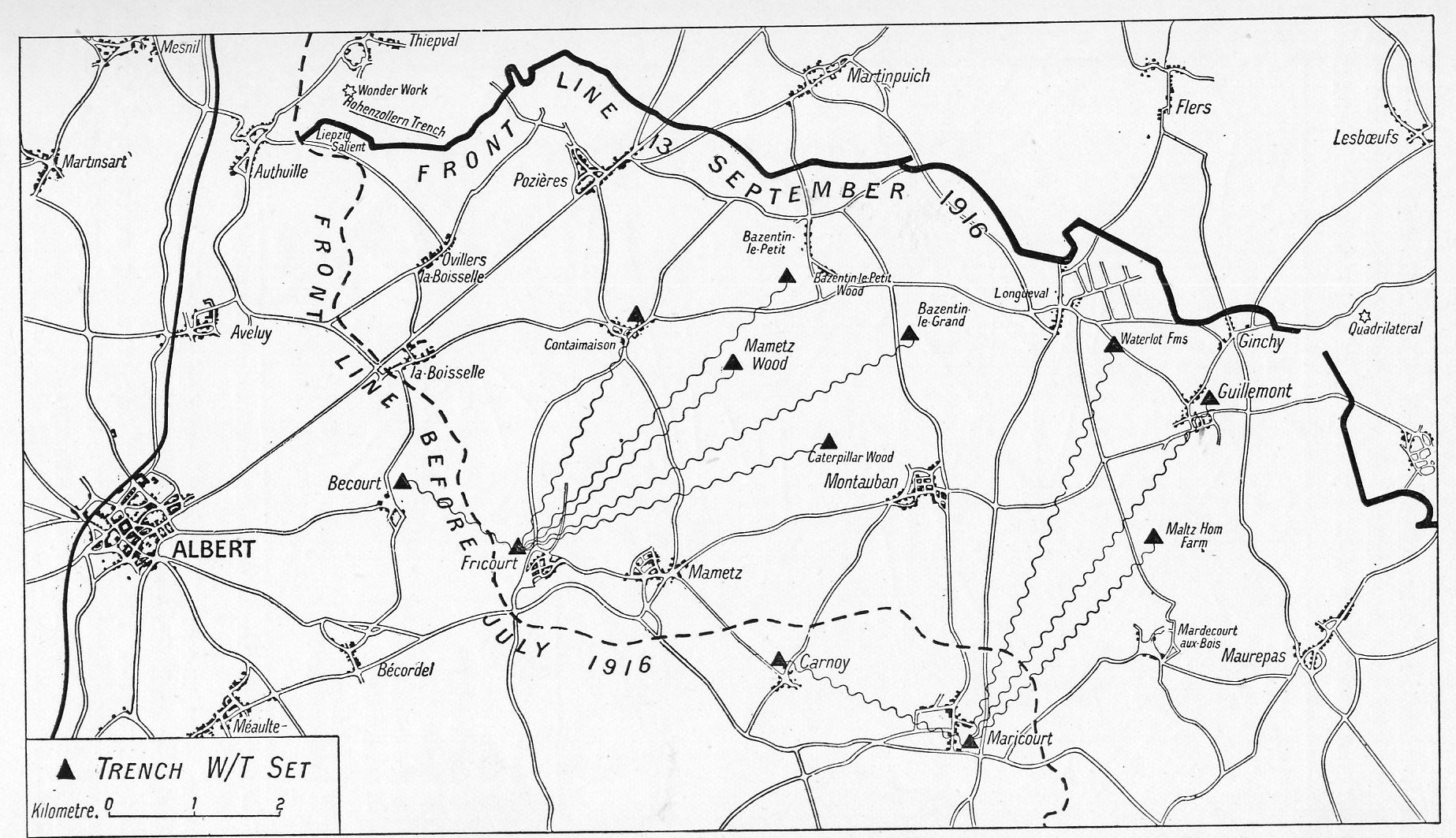
One of the earliest radios to be used in the trenches was the 50-watt Trench Set, also known as the BF Set (Figure 2) which was used for communication from Brigade to Division. This went into action in the Battle of Loos in September 1915 and in the first Battle of the Somme on July 1st 1916. The transmitting portion of set was based on the design of the No 1 Aircraft Spark set. The receiving portion used a carborundum crystal detector. It was powered from an accumulator and also required dry-cell batteries for biasing the carborundum crystal and an internal test buzzer.
Its range was 3.7km with aerials mounted on masts but this reduced to 1.1km when the aerial was run close to the ground.
Careful planning of frequencies was required in order to minimize interference from neighbouring spark transmitters, a problem much simplified when CW sets came into use.
The BF set was used extensively during the second half of the war and approximately 1200 were manufactured.
130-watt Wilson Trench Set & Short Wave Tuner Mk. III
The Wilson Transmitter was used primarily for Division to Corps communication and Corps Directing Station. This set came into service about the same time as the BF Trench Set. It had a fixed spark gap with a motor-driven, high-speed interrupter rather than the slower magnetic interrupter. The greater number of sparks produced a musical note in the headphones, making the Morse signal more easy to hear through interference. The transmitter had the same frequencies as the BF set and the higher power meant that the range was up to 8.3km. The set was supplied by an accumulator.
Tuner Short Wave Mk. III*
The Mk. III version of this tuner was introduced in 1916 and the Mk. III* in 1918. Its prime purpose was to receive Morse messages from aircraft flying over the trenches but it was also used with the Wilson Set. The receiver used a crystal detector and there was a buzzer for calibrating and testing the tuner. Total production was 766 transmitters and 6595 receivers.
Later valve Developments
Towards the end of 1915 an entirely new type of valve was developed under Colonel (later General) Gustav Ferrié who was in charge of the French Military Telegraphic Service. The construction was very simple: it had a straight tungsten filament, a spiral grid and a cylindrical anode. It was evacuated to a low pressure and during the manufacturing process the glass and metal parts were heated to a sufficient temperature to release occluded gases. The valve, known as the TM, was immensely successful and widely used throughout the war, over 100,000 of which were made by the two French companies, Fotos and Métal. By 1916 it was being manufactured in Britain as the R-valve.
There were many variants, including the Air Force C and D, and the low-power transmitting valves B, F and AT25. Two higher power transmitting valves, introduced in late 1917, were the T2A and T2B which had 250 watt dissipations. These were used by the RFC (later RAF) in ground station CW transmitters.
One problem with the TM and R-valve was the high capacitance between the anode and grid. This made its use as an RF amplifier very difficult because energy fed back from the output of the valve to its input was liable to cause unwanted oscillation.
To overcome this Round of the Marconi Company developed the type Q in 1916 which featured small size and low capacitance. It had a straight tungsten filament terminated by the two pointed metal caps at each bend of the bulb. Both the anode and grid connections were taken to two further caps near one end of the tubular glass bulb. The Q was primarily intended as a detector but it was also used as both an amplifier. It overall length was 73mm and the bulb diameter 16mm. Later in the war Round designed the V24 which was better suited as an RF or AF amplifier.
Later army radios
Valve radios first made their appearance in 1916. One of the earliest was the Tuner Aircraft Valve Mk. I but this was not made in significant numbers.
W/T Set Forward Spark 20 watt “B”
This set came into service in 1917 and was also known as ‘The Loop Set’ and was used for forward communication. There were both Rear Stations and Front Stations sets, with two versions of each. There were also separate receivers for the Rear and Forward Stations. These receivers had two valves which were either the French TM or the British R.
The transmitter had a fixed spark gap powered directly from an induction coil operating in a similar way to the BF Trench Set. The power for the stations was supplied by an accumulator and a 32-volt HT battery.
Approximately 4000 of the transmitters and receivers were manufactured.
W/T Trench Set Mk. I 30-watt
The first CW sets for field use were made in 1916 and used a single valve for both the transmitter and receiver circuits and was used for forward communication by ICW. The Mark 1* version came into service in 1917 and incorporated a high-speed interrupter to modulate the transmission.
W/T Set Trench CW Mk. III*
This (CW) set comprised a transmitter and a heterodyne receiver in separate boxes. It came into service in 1917 and was used for forward area telegraphy.
The transmitter was rated at 30-watts and had a range of 3.7km. It utilised two valves which were either the type B or AT25.
The receiver had two R valves. The first of these was used in a heterodyne circuit and the second as an audio frequency amplifier for the Morse signal.
The complete set also included a heterodyne wavemeter, Selector Unit and Rectifier Unit.
Total production was a little under 3000 for both the transmitter and the receiver and approximately 400 of the Selector Units.
Telephone Wireless Aircraft Mk. II
The Telephone Aircraft Mk. II came into service in 1917. It had two B or F valves, one being used for control and other an output valve. An accumulator was used to supply the valve’s filaments and the HT was derived from a wind-driven generator. It had a range of 3.2km to other aircraft and 2km to ground stations.
The aerial was a trailing wire of length 100–150ft with a lead weight at the end.
Earlier attempts to fit radio telephones in aircraft had been hampered by the high background noise from the aircraft’s engine. This problem was alleviated by the design of a helmet with built-in microphone and earphones to block much of the noise.
A typical receiver for use with this transmitter was the Tuner Aircraft Mk III which had three R valves, one for the detector and two for low-frequency amplification.
Conclusions
The army was very slow to adopt wireless for communication on the battlefield and relied too much on communication by cable. There was a genuine fear that wireless would be intercepted by the enemy but this was also true with cable. The cable used was being constantly severed by shell fire and the passage of tanks across the battlefield.
Apart from a few high-powered transmitters that played a minor role in the war, the first wireless transmitters were fitted in aircraft during 1915. These were used to communicate with crystal receivers on the ground to direct artillery fire.
The first trench sets went into service towards the end of 1915. From this time onward the army came slowly round to realizing that wireless communication was a more reliable way to communicate than by cable, particularly when troops were moving rapidly forwards or backwards.
The most significant technical breakthrough came following the development of the TM valve in France. This, and its many derivatives, enabled reliable valve transmitters and receivers to be produced from 1916 onwards. It now became possible to make CW transmitters, which were far superior to the spark sets.
By mid-1917 the army at last accepted that radios were the best way to communicate and increasing numbers of these came into service in the final year of the war.
Acknowledgements
I should like to thank Nick Kendall-Carpenter and his archive staff at the Royal Signal Museum, Blandford, Louis Meulstree and John Liffen of the Science Museum for their valuable assistance.
About the Author: Keith Thrower OBE is author of British Radio Valves: The Vintage Years – 1904-1925 and British Radio Valves: The Classic Years 1926-1946.
This article is based on the paper Keith gave at “Making Telecommunications in the First World War” in Oxford on 24 January 2014. See our events page for full details including the abstract, PowerPoint slides and full version of Keith’s paper.
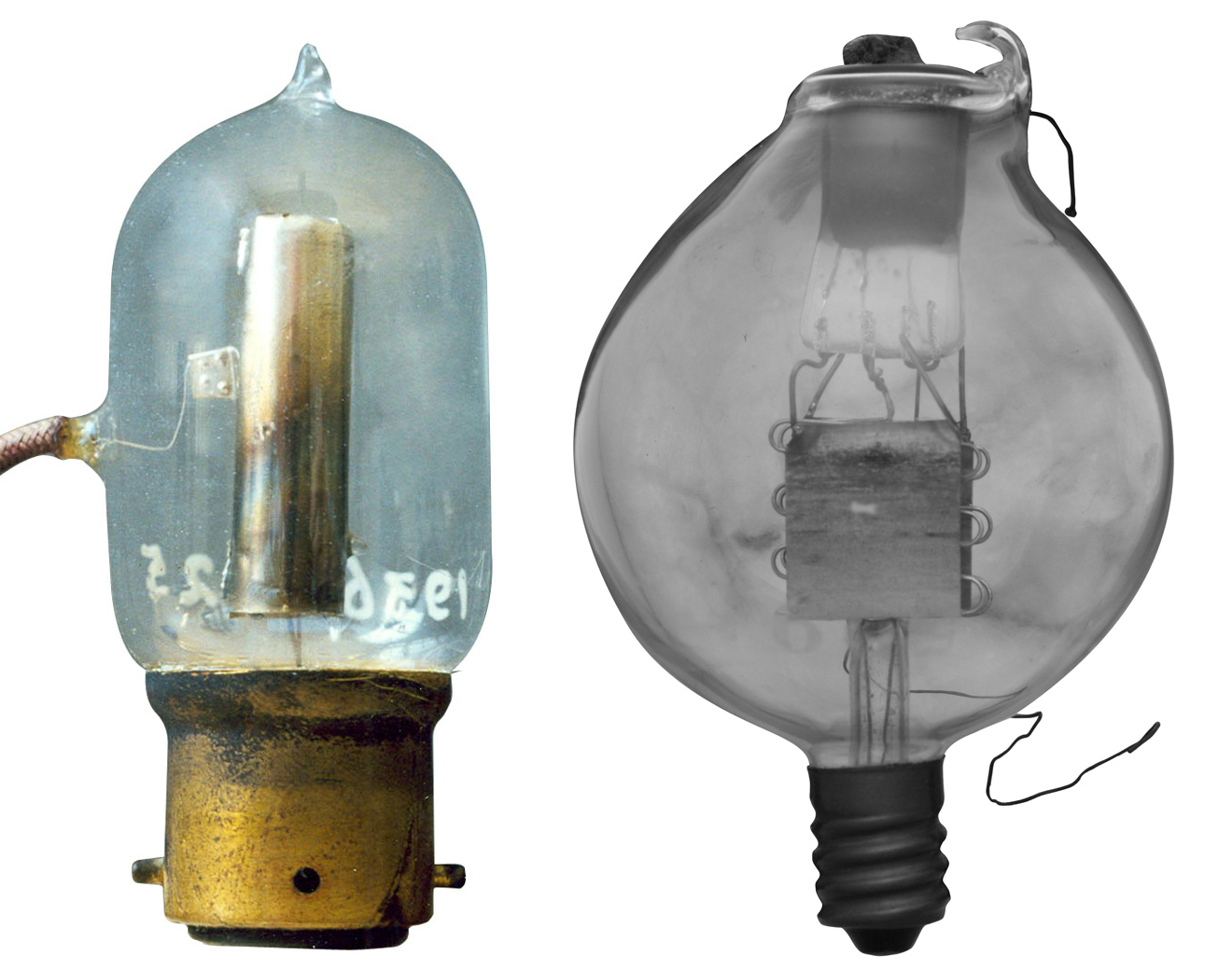
Fig. 1 (left) Commercial version of Fleming diode; (right) BT-H version of the de Forest Audion triode, a ‘soft’ valve erratic in operation.
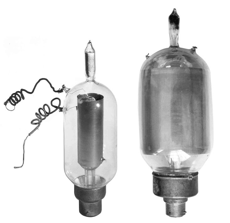
Fig. 2: Marconi-Round C and T valves of 1913. These were both ‘soft’ valves. The C was a receiver valve for use as a detector or RF amplifier. The T was a transmitter valve.
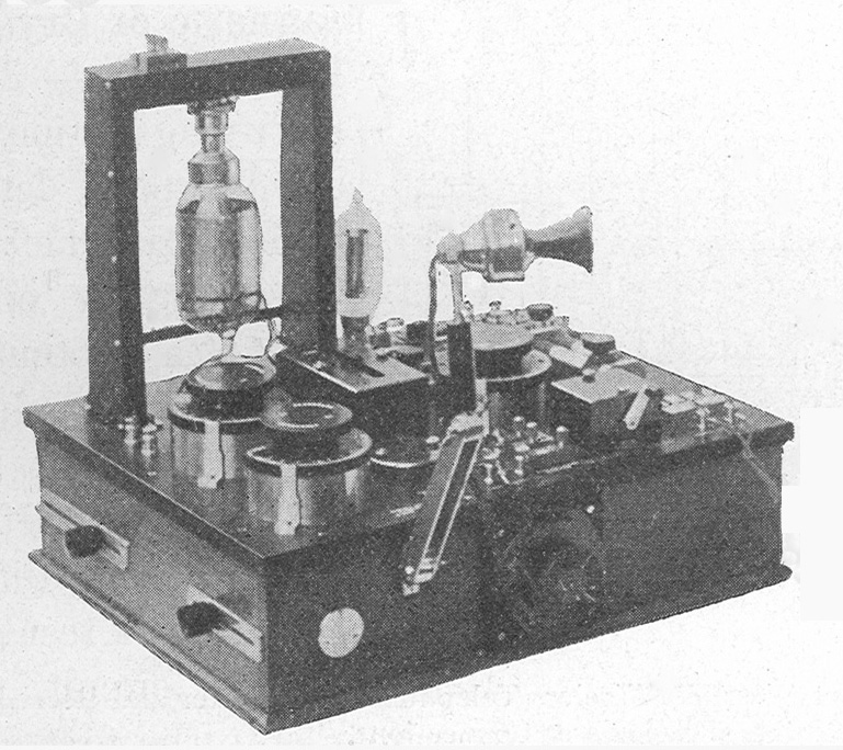
Fig 3: Marconi Short Distance Wireless Telephone Transmitter and Receiver. This set used a C valve in the receiver, connected as an RF amplifier with regenerative feedback to increase its gain and provide improved selectivity. Detection was by a carborundum crystal. For transmission there was a single T.N. valve (seen mounted in the frame) and this was connected as an oscillator. It is believed that Marconi used this set for CW voice trials in 1914.
Fig 4: Marconi 1.5 kW spark generator of approx. 1911 design. Note the rotating spark gap seen at the front.

Fig 5: Marconi 1.5 kW spark Pack Set showing the operating cart with the crystal set receiver.
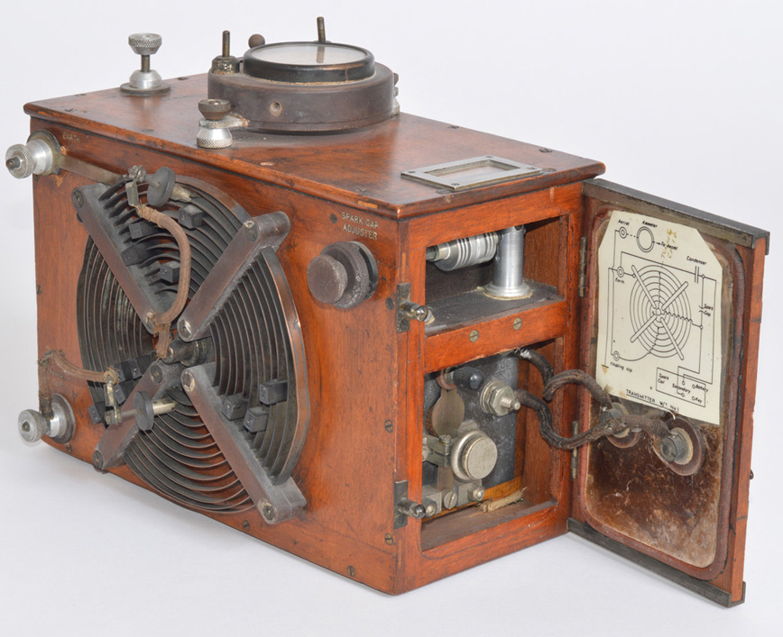
Fig 6: No. 1 Aircraft Transmitter Spark. 30-watt input. Note the spark gap on the top right inside the cabinet with the adjustment for the gap at the front.
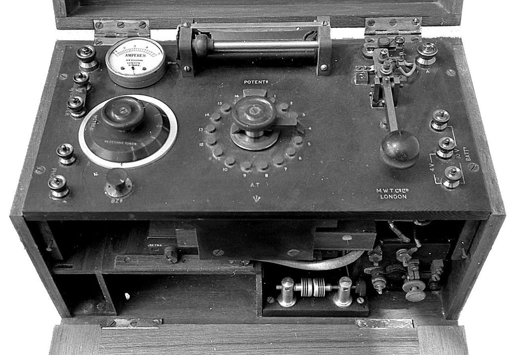
Fig 7: W/T Trench Set 50 Watt D.C. (Also known as the BF set) The spark gap is clearly seen at the bottom.
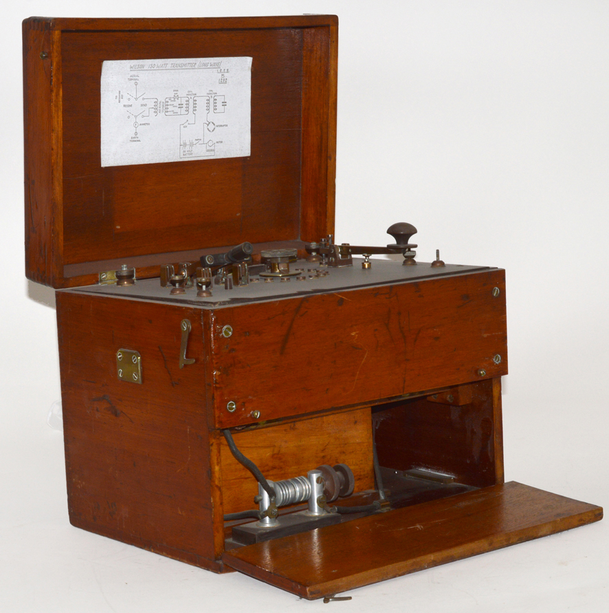
Fig 8: W/T trench Set 130-watt Wilson. Transmitter only; used with Tuner Short Wave Mk. III.
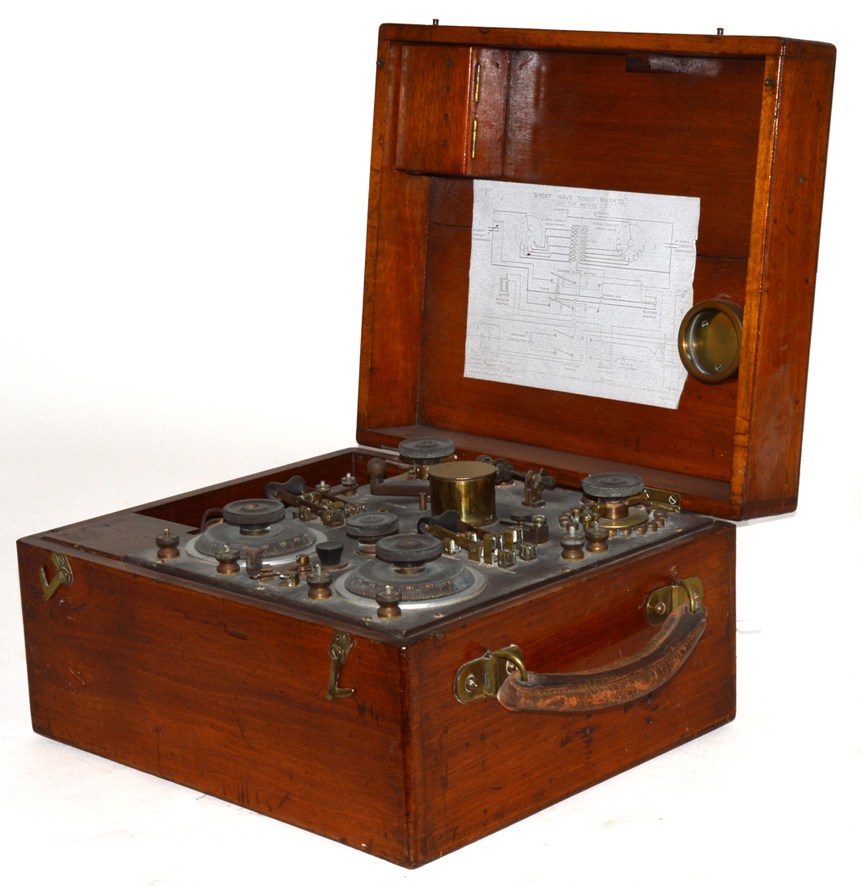
Fig 9: Tuner Short Wave Mk. III*. This receiver has both a carborundum and a Perikon detector.
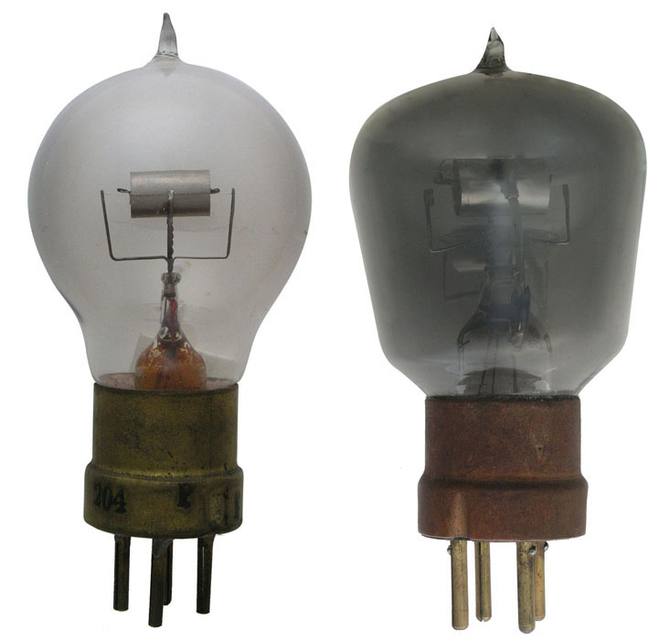
Fig. 10a & 10b: French TM and Osram F valve. The TM was a general-purpose valve used mainly as a detector or an AF amplifier. The F was a low-power transmitting valve similar in construction to the TM.
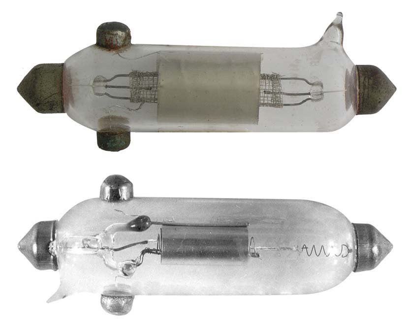
Fig. 10c & 10d: Top Q, bottom V24. The Q went into production at Edison Swan in 1916 and was used mainly as a detector. The V24 probably went into production at the end of 1917 or early in 1918. It was used as both an RF and an AF amplifier.
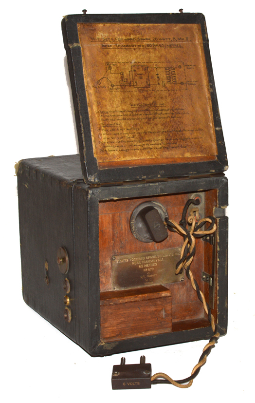
Fig. 11: W/T Forward Spark 20-watt “B” transmitter.
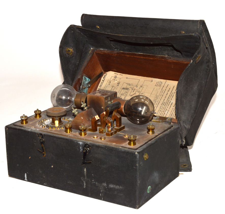
Fig. 12: W/T Forward Spark 20-watt “B” receiver.
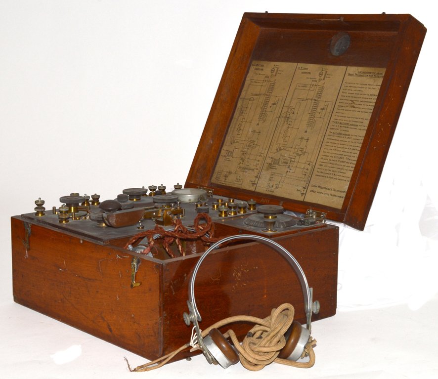
Fig 13: W/T Trench Set Mk. I. Combined transmitter & receiver.
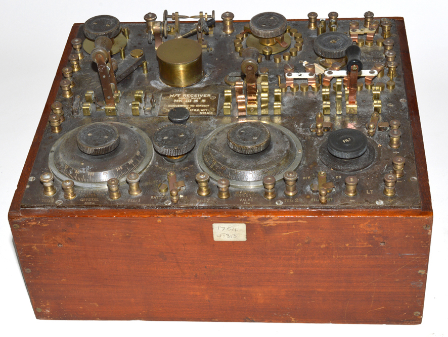
Fig 14: W/T Receiver Short Wave Mk. III**.
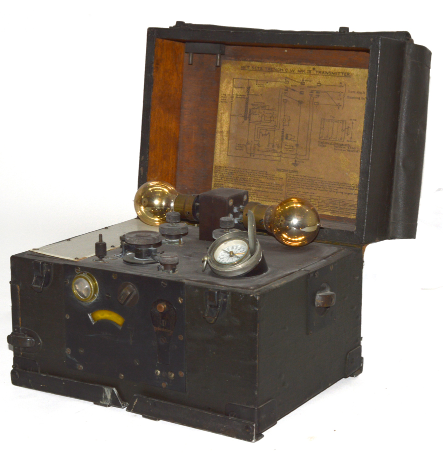
Fig 15: W/T Trench Set Mk III* transmitter.

Fig 16: W/T Trench Set Mk III* receiver.
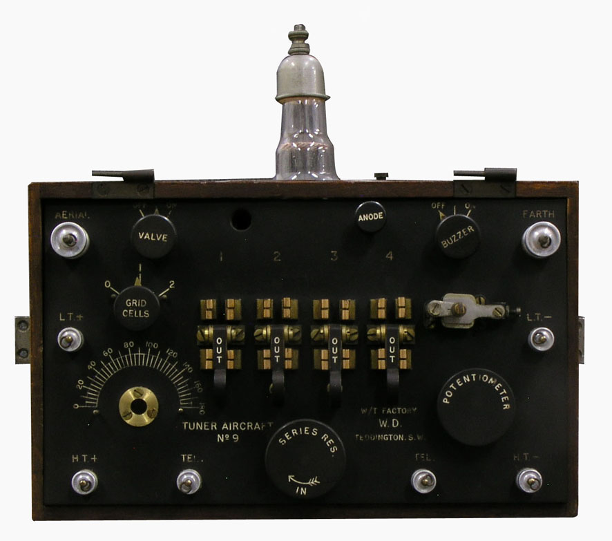
Fig. 17: Tuner Aircraft No. 9. This went into service in 1916.
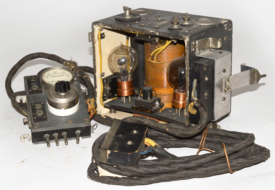
Fig 18: Telephone Wireless Aircraft Mk. II, complete with remote control and headphones.